Energetic-beam detection apparatus including temperature-controlled selenium detector

a technology of energy beam and detection apparatus, which is applied in the direction of conversion screen, radio frequency control device, instruments, etc., can solve the problems of increasing the complexity of the manufacturing process and the manufacturing cost, deteriorating the characteristics of the photoconductive layer during the photoetching process, and inability to withstand such a high temperatur

Inactive Publication Date: 2002-10-22
FUJIFILM CORP +1
View PDF17 Cites 64 Cited by
  • Summary
  • Abstract
  • Description
  • Claims
  • Application Information

AI Technical Summary

Benefits of technology

Another object of the present invention is to provide an energetic-beam detection apparatus including a selenium detector comprised of a substrate and an energetic-beam absorber which is formed on the substrate and contains selenium, wherein decrease in the practical lifetime of a selenium detector due to softening or development of bulk crystallization of selenium in a high-temperature environment can be suppressed, and exfoliation of the energetic-beam absorber from the substrate due to thermal stress caused by operation in a low-temperature environment can be prevented.
(xi) In the energetic-beam detection apparatus according to the fifth aspect of the present invention having the feature (vi), the low-side temperature control unit may comprise a warming unit which warms the selenium detector. The warming unit may be a warm-air blower, heater, or the like. When the low-side temperature control unit comprises the warming unit, the temperature of the selenium detector can be easily raised to or above the predetermined lower limit.

Problems solved by technology

), and the a-Se which constitutes the photoconductive layers cannot withstand such a high temperature.
Therefore, the characteristics of the photoconductive layers deteriorate during the photoetching process.
In addition, since the alkali developer solution used in the process of developing the photoresist generates harmful gas on contact with the a-Se, special provision for elimination of the harmful gas increases the complexity of the manufacturing process and the manufacturing cost.
However, when the above-mentioned selenium detectors (solid-state radiation detectors) are used for a long time in a high-temperature environment, the temperature of the solid-state radiation detectors increases.
Generally, the dark resistance characteristics of amorphous selenium films tend to deteriorate over time even under normal use.
Therefore, the practical lifetimes of the selenium detectors are limited.
Further, when the temperature exceeds 50.degree. C., the selenium films are softened, and the practical lifetimes can be seriously reduced.
In particular, when the operation of the selenium detector is suddenly started in a situation in which thermal stress is caused at the boundary between the glass substrate and the selenium multilayer film by low temperature, and the selenium multilayer film is not yet separated from the glass substrate by exfoliation, exfoliation of the selenium multilayer film is likely to occur since a temperature difference between the selenium multilayer film and the glass substrate is caused by the start of the operation.

Method used


Image

  • Energetic-beam detection apparatus including temperature-controlled selenium detector
  • Energetic-beam detection apparatus including temperature-controlled selenium detector
  • Energetic-beam detection apparatus including temperature-controlled selenium detector

Examples


first embodiment

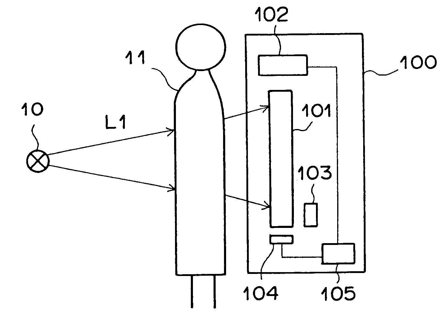
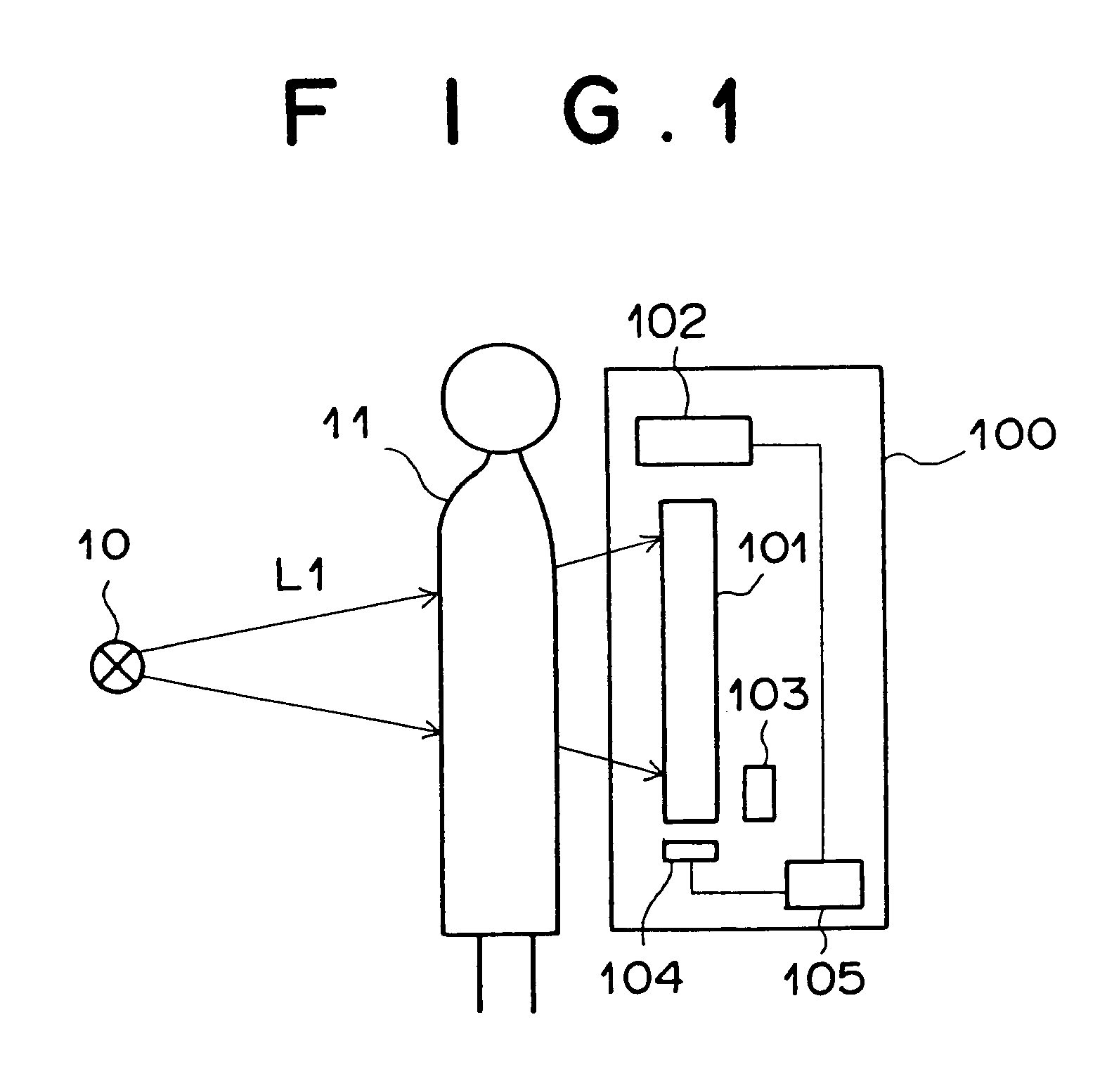
FIG. 1 is a diagram illustrating an outline of a radiographic-image pickup-and-readout system using an energetic-beam detection apparatus as the first embodiment of the present invention. The radiographic-image pickup and readout system of FIG. 1 comprises a radiation source 10 and a pickup-and-readout apparatus 100 as the energetic-beam detection apparatus. The pickup-and-readout apparatus 100 comprises a solid-state radiation detector 101, a current detection unit 102, an LED array 103, a thermistor 104, and a operation suppressing unit 105. The solid-state radiation detector 101 is a flat-panel type selenium detector. The current detection unit 102 reads out image information from the solid-state radiation detector 101 as a current value. The LED array 103 scans the solid-state radiation detector 101 with reading light for exposing the solid-state radiation detector 101 to the reading light. The thermistor 104 detects the temperature of the solid-state radiation detector 101.

FIG....

second embodiment

FIG. 3 is a diagram illustrating an outline of a radiographic-image pickup-and-readout system using an energetic-beam detection apparatus as the second embodiment of the present invention. In FIG. 3, elements having the same reference numbers as FIG. 1 have the same functions as the corresponding elements in FIG. 1, and the detailed explanations of the same elements as FIG. 1 are not repeated.

The radiographic-image pickup and readout system of FIG. 3 comprises a radiation source 10 and a pickup-and-readout apparatus 200 as the above energetic-beam detection apparatus. The pickup-and-readout apparatus 200 comprises a solid-state radiation detector 101, a current detection unit 102, an LED array 103, a thermistor 104, a notification control unit 201, and an alarm unit 202. The solid-state radiation detector 101 is a flat-panel type selenium detector. The current detection unit 102 reads out image information from the solid-state radiation detector 101 as a current value. The LED array...

third embodiment

FIG. 4 is a diagram illustrating an outline of a radiographic-image pickup-and-readout system using an energetic-beam detection apparatus as the third embodiment of the present invention. In FIG. 4, elements having the same reference numbers as FIG. 1 have the same functions as the corresponding elements in FIG. 1, and the detailed explanations of the same elements as FIG. 1 are not repeated.

The radiographic-image pickup and readout system of FIG. 4 comprises a radiation source 10 and a pickup-and-readout apparatus 300 as the above energetic-beam detection apparatus. The pickup-and-readout apparatus 300 comprises a solid-state radiation detector 101, a current detection unit 102, an LED array 103, a thermistor 104, a temperature control unit 301, a heater 302, and a fan 303. The solid-state radiation detector 101 is a flat-panel type selenium detector. The current detection unit 102 reads out image information from the solid-state radiation detector 101 as a current value. The LED a...


PUM


Abstract

In an energetic-beam detection apparatus having a selenium detector which includes a substrate and an energetic-beam absorber being formed on the substrate and containing selenium, a temperature detecting unit detects a temperature of the selenium detector, and a temperature control unit controls the temperature of the selenium detector so that the temperature is maintained in a predetermined range when the selenium detector is in operation. Alternatively, when the temperature of the selenium detector is outside a predetermined range, an operation suppressing unit suppresses the operation of the selenium detector, or a notification unit notifies a user of the deviation of the temperature of the selenium detector from the predetermined range.

Description

The subject matters disclosed in this specification are related to the subject matters disclosed in the following copending, commonly-assigned U.S. patent applications:(1) U.S. Ser. No. 09 / 136,739 filed by Shinji Imai on Aug. 19, 1998, now U.S. Pat. No. 6,268,614 and entitled "ELECTROSTATIC RECORDING MEMBER, ELECTROSTATIC LATENT IMAGE RECORDING APPARATUS, AND ELECTROSTATIC LATENT IMAGE READ-OUT APPARATUS," corresponding to Japanese patent application No. 10-232824, which is disclosed in Japanese Unexamined Patent Publication No. 2000-105297; and(2) U.S. Ser. No. 09 / 385,443 filed by Satoshi Arakawa on Aug. 30, 1999 and entitled "RADIATION IMAGE DETECTING SYSTEM," corresponding to Japanese patent application No. 10-243379, which is disclosed in Japanese Unexamined Patent Publication No. 2000-137080.The contents of the above copending, commonly-assigned U.S. patent applications and the corresponding Japanese patent applications are incorporated in this specification by reference.1. Fie...

Claims


Application Information

Patent Timeline
Patent Type & Authority Patents(United States)
IPC IPC(8): G01T1/00G01T1/17G01T7/00G03G5/02G01T1/24G01T1/16G01T1/29G21K4/00
CPCG01T1/244G01T1/246
Inventor AGANO, TOSHITAKA
Owner FUJIFILM CORP
Why Eureka
Try Eureka