Dual band framing reconnaissance camera

a reconnaissance camera and band framing technology, applied in the field of aerial reconnaissance photography and camera systems, can solve the problems of distorted geometric and geospatial images, and inability to achieve geometric and geospatial distortion images,

Inactive Publication Date: 2002-11-05
THE BF GOODRICH CO
View PDF10 Cites 45 Cited by
  • Summary
  • Abstract
  • Description
  • Claims
  • Application Information

AI Technical Summary

Problems solved by technology

These operational issues were hostage to the technological limitations of the day.
The disadvantage is that each line of exposed imagery was taken from a different perspective, hence the scanning system inherently was prone to creating geometrically and geospatially distorted images.
Again, the disadvantage of this method was that imagery was obtained from a different perspective as the aircraft moved, resulting in geometrically and geospatially distorted images.
The disadvantage of step framing cameras was that the stepping action was very difficult to accomplish with the whole camera, therefore it had to be broken into a scan head that performed the stepping and an image de-rotation mechanism, both of which were tied together by a synchronized drive system.
However, the implementation of such a camera presents...

Method used


Image

  • Dual band framing reconnaissance camera
  • Dual band framing reconnaissance camera
  • Dual band framing reconnaissance camera

Examples


Embodiment Construction

The optical system design of the subject camera is driven by the need to illuminate a large focal plane image recording medium and by space constraints, namely the total axial length and the total diameter, which have to be accounted for in potential aircraft installation applications. Thus, while the particular optical design described herein is optimized for a given set of spatial constraints, variation from the illustrated embodiment is considered to be within the scope of the invention.

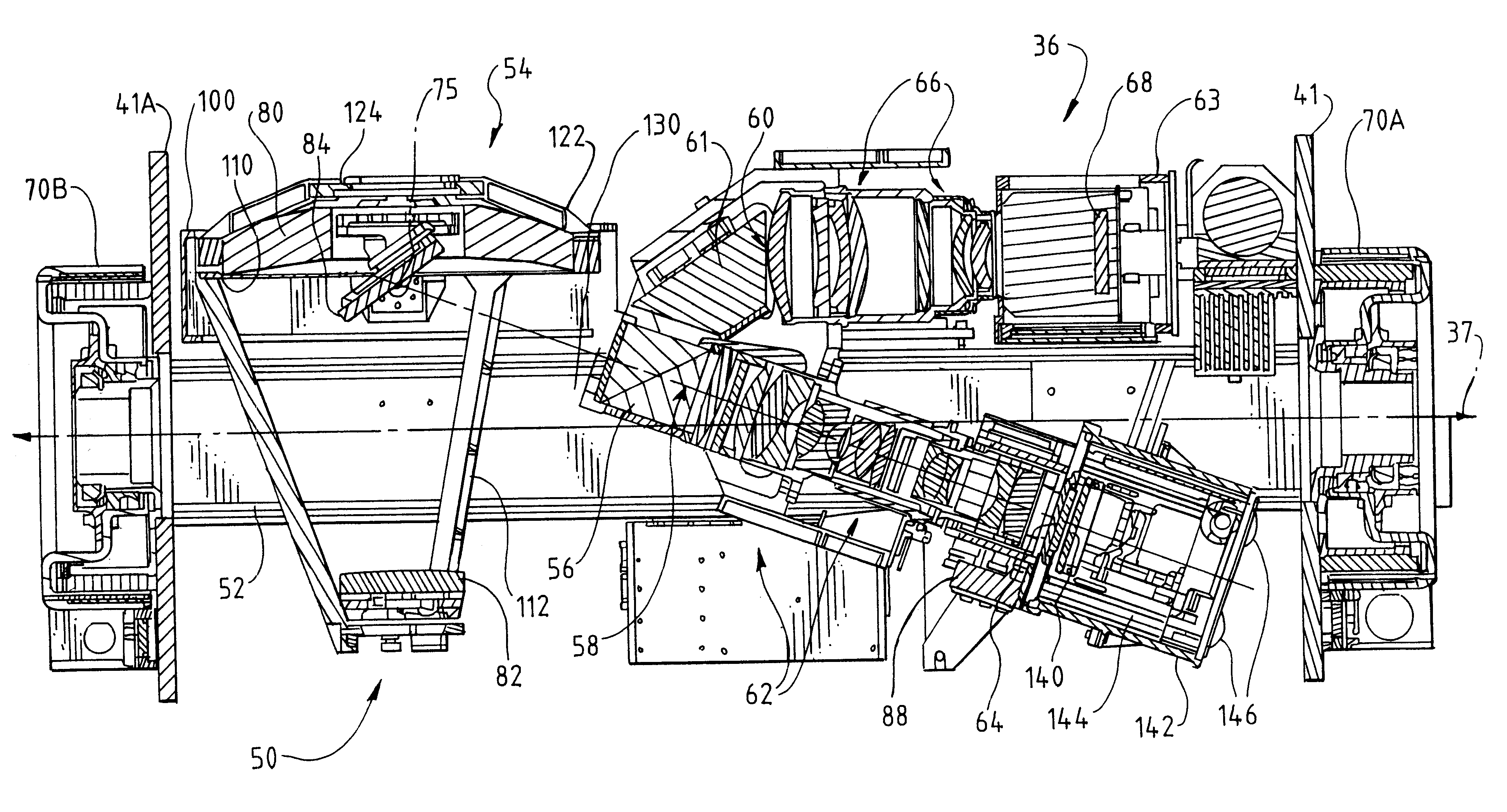
The optical system 50 of FIGS. 3 and 4 represents a 50-inch, F / 4 optical system designed to operate over an extended spectral region. The objective lens module consists of the Cassegrain optical subsystem 54, comprising the primary and secondary mirrors 80 and 82. The azimuth mirror 84 is utilized to redirect the image forming light bundles into the remainder of the optical system, namely the spectrum dividing prism and the relay lenses and other optical components in the optical paths 58 and 60.

R...


PUM


Abstract

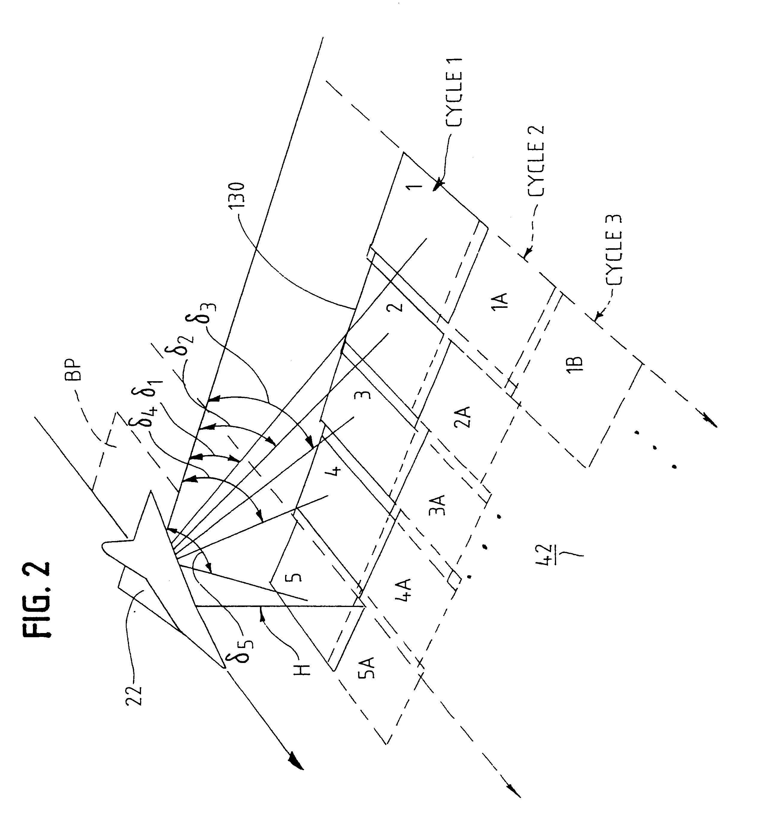
A framing aerial reconnaissance camera is described which has a Cassegrain optical system forming an objective lens that directs radiation to a spectrum-dividing prism. The prism directs radiation in the visible portion of the electromagnetic spectrum into a first optical path having a two-dimensional image-recording medium, such as a framing CCD array. Radiation in the infrared (IR) band of the spectrum is directed to a second optical path, which has a two-dimensional framing IR-sensitive image-recording medium. The entire camera can be either rotated about the aircraft roll axis in a continuous fashion or stepped in a series of steps to generate frames of imagery, providing panoramic coverage of the scene across the line of flight in two bands of the spectrum simultaneously.

Description

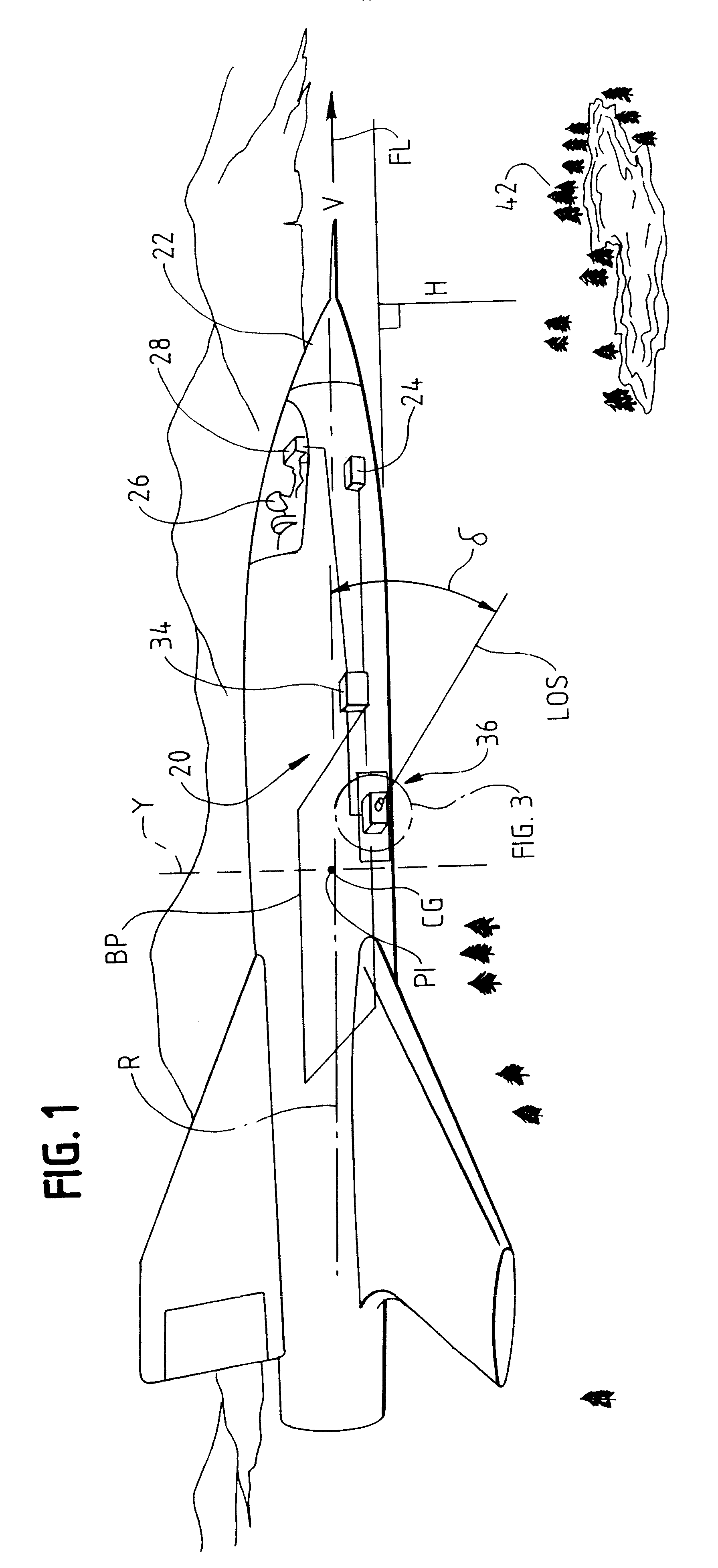
A. Field of the InventionThis invention relates generally to the field of aerial reconnaissance photography and camera systems used for such photography. More particularly, in a principal aspect the invention relates to a reconnaissance camera that generates frames of imagery of terrain in different portions or bands of the electromagnetic spectrum simultaneously.The invention also relates to a novel method by which a camera compensates for image motion due to both camera rotation and forward motion of the aircraft in which the camera is installed. Such image motion compensation allows for high-resolution images to be obtained from the camera system.B. Description of Related ArtLong Range Oblique Photography (LOROP) cameras have been developed as a result of the need to obtain clear, high resolution pictures from longer ranges, typically from 10 to 50 nautical miles from the terrain of interest. The advent of LOROP cameras was an outgrowth of development of weapons technology, which...

Claims


Application Information

Patent Timeline
IPC IPC(8): G01C11/02G01C11/00G02B7/18G02B17/08
CPCG01C11/025G02B7/18G02B17/0808G02B17/0852G02B17/0896H04N5/2251H04N23/50
Inventor PARTYNSKI, ANDREW J.BERAN, STEPHEN R.BAKER, ALLIE M.JONES, JOHNWYATT, STEPHAN
Owner THE BF GOODRICH CO
Why Eureka
Try Eureka