
Secure partitioning of shared memory based multiprocessor system

Inactive Publication Date: 2002-11-12
IBM CORP
View PDF5 Cites 112 Cited by
  • Summary
  • Abstract
  • Description
  • Claims
  • Application Information

AI Technical Summary

Benefits of technology

It is an object of this invention to provide an apparatus and method for flexible and secure partitioning of shared memory based multiprocessor systems utilizing commodity hardware such as central processing units, caches, memory banks, IO controllers, IO devices and interrupt controllers.

Problems solved by technology

Due to reasons described below, it is very difficult to partition a commodity based shared memory based multiprocessor without modification of hardware and system software.
For example, a malicious or a faulty OS can corrupt another partition by gaining access to the other partition's memory space.
When OS kernel changes are possible, memory access problems can be limited, but not fully eliminated.
Unfortunately, wild writes can still cause a problem: in the case where special purpose registers are used to point to the current address table (e.g. Intel-IA32, Dec-Alpha) one cannot catch illegally generated "update-translation-table" instructions, which point to translation tables outside the designated translation table memory range.
Furthermore, this solution comes at a price, namely, the emulation of privileged instructions can introduce a runtime overhead.
Even worse, licensing issues of commodity operating systems often prohibit such deployment.
Unfortunately, due to very tight timing constraints that govern modern system buses, such remapping devices can not be located between the processor and the bus but must be located close to or within the memory controller.
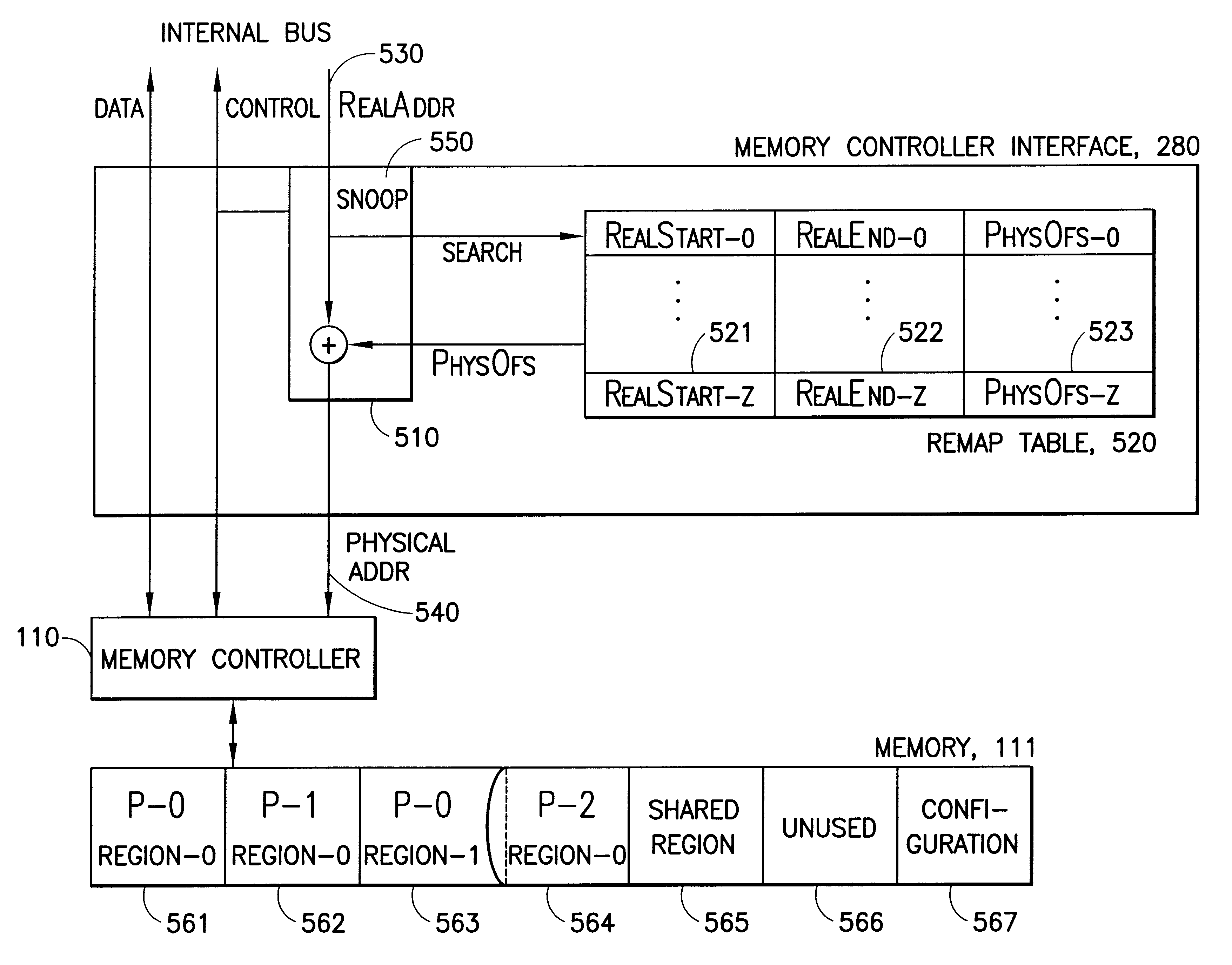
However, placing a remapping device with the memory controller, rather than the processor core, creates a cache coherence problem, due to the fact that two partitions can put the same real memory address out on the system bus, yet for different partitions, the same real address refers to different memory.
However, providing one's cache content to a processor in a different partition violates the memory consistency model and leads to faulty behavior since the real address (A) in two different partitions is not backed by the same memory.
Nevertheless, when utilizing commodity based microprocessors, besides physical memory separation, establishment of proper distinct cache coherence domains poses another significant problem in memory partitioning.
As above discussions have illustrated, providing a fault contained, secure partitioning of shared memory based multiprocessor systems with techniques known in the prior art is quite cumbersome and basically impacts every system interface component that attaches a commodity item (e.g. CPU, IO device, Memory Controller) to the system bus.

Method used


Image

  • Secure partitioning of shared memory based multiprocessor system
  • Secure partitioning of shared memory based multiprocessor system
  • Secure partitioning of shared memory based multiprocessor system

Examples


Embodiment Construction

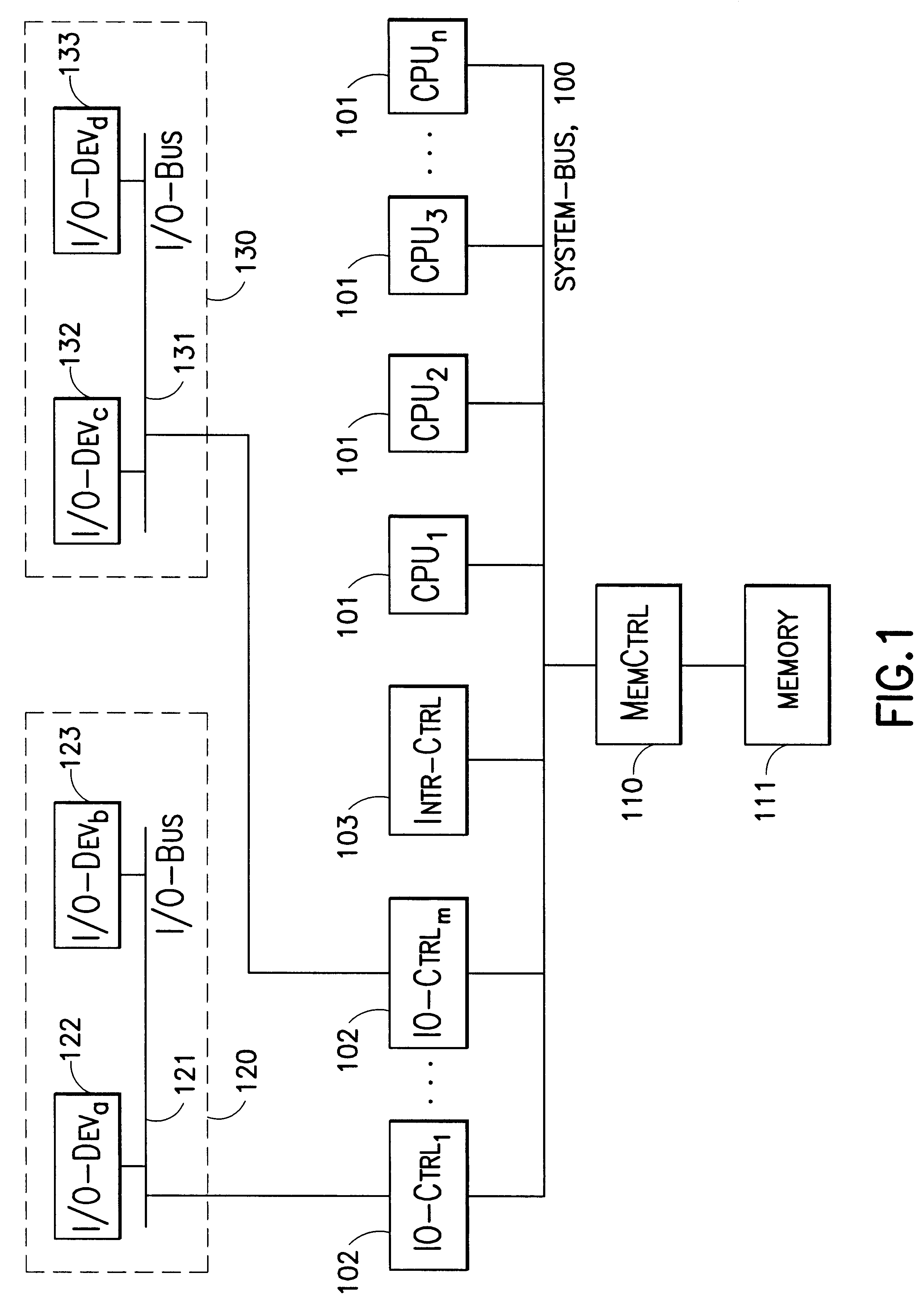
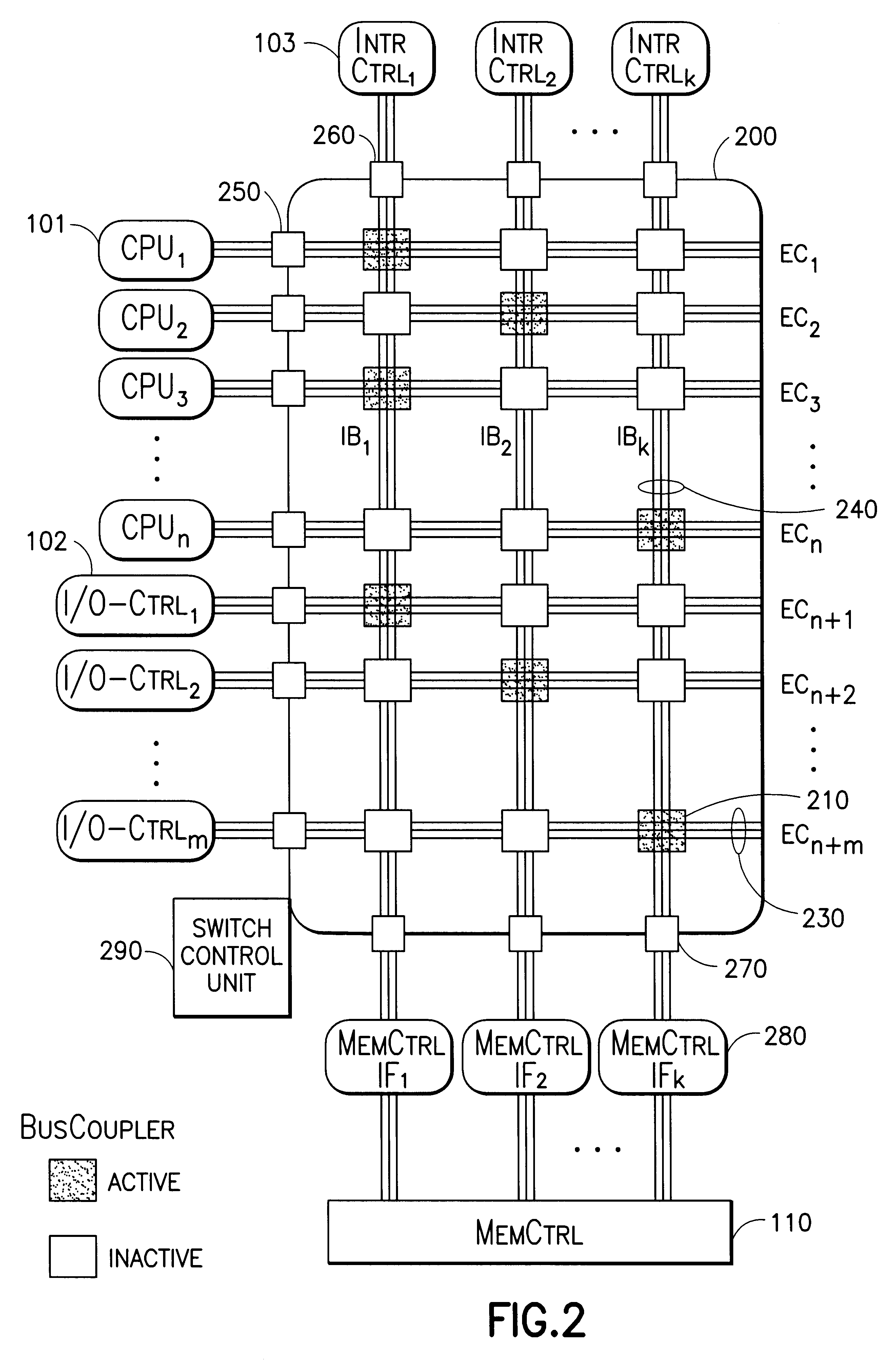
The general architecture and apparatus in a preferred embodiment is shown in FIG. 2. It consists of a bus-coupling crossbar switch (200). The crossbar switch provides a set of internal buses IB.sub.1, IB.sub.2, . . . , IB.sub.k (240). These buses replicate the system bus (100) typically found in a shared memory based system depicted in FIG. 1. Each of these internal buses IB.sub.i carries all signals of the system bus, i.e. address lines, data lines and control lines. The presence of these three classes is emphasized in the drawing of (240). The number k of internal buses determines the number of partitions that are supported by the crossbar switch.

In addition to the replicated internal system buses, the crossbar switch (200) provides a set of external connector buses EC.sub.1, EC.sub.2, . . . EC.sub.n+m (230). Each EC.sub.j (230) provides the same address lines, data lines and control lines as the internal system buses. A single system component, either a CPU (101) or a I / O Control...


PUM


Abstract

A method and apparatus for sharing memory in a multiprocessor computing system. More specifically, this invention provides a number of system buses with each bus being connected to a respective memory controller which controls a corresponding partition of the memory. Any one of the processors can use any one of the system buses to send real addresses to the connected memory controller which then converts the real addresses into physical addresses corresponding to the partition of memory that is controlled by the receiving memory controller. The processors can be dynamically assigned to different partitions of the memory by via a switching mechanism.

Description

This invention relates to the field of shared memory based multiprocessor systems. More specifically, the invention relates to an apparatus that is capable of partitioning a shared memory based multiprocessor system into independent, fault contained computing domains.Modern computer systems are increasingly comprised of shared memory based multiprocessor systems (SMP). At the same time computing has witnessed a sheer outburst in different types of applications, from user oriented desktop applications, such as word processing, to more enterprise oriented tasks such as web servers, databases and electronic mail services. Each type of such applications can carry significantly different importance and criticality as well as technical maturity. It, therefore, makes sense to group applications with similar reliability, availability and serviceability (RAS) requirements into an independent domain and ensure that faults are contained within that domain, i.e. fault in one domain do not affec...

Claims


Application Information

Patent Timeline
IPC IPC(8): G06F12/02
CPCG06F12/0284
Inventor FRANKE, HUBERTUSGIAMPAPA, MARK EDWINJANN, JOEFONJOSEPH, DOUGLAS JAMESPATTNAIK, PRATAP CHANDRA
Owner IBM CORP
Learn More