Springless poppet valve system

a poppet valve and springless technology, applied in the direction of valve arrangements, machines/engines, mechanical equipment, etc., can solve the problems of increasing the force and stress applied to the components of the valve train, and increasing the actuation speed of the valve. the effect of actuation speed and less cost of manufacture and assembly

Inactive Publication Date: 2002-12-03
PALUMBO CHRIS
View PDF10 Cites 20 Cited by
  • Summary
  • Abstract
  • Description
  • Claims
  • Application Information

AI Technical Summary

Benefits of technology

A more specific object of the present invention is to provide a poppet valve system as characterized above which can achieve higher valve actuation speeds than existing springless poppet valve systems.
Another object of the present invention is to provide a poppet valve system as characterized above which is less costly to manufacture and assemble than existing springless poppet valve systems.
A further object of the present invention is to provide a poppet valve system as characterized above which requires less maintenance than existing poppet valve systems.

Problems solved by technology

These conventional poppet valve systems, however, are limited with regard to speed at which the valves can be actuated.
In particular, increasing the actuation speed of the valve necessarily increases the force and stress applied to the components of the valve train.
This increased mass, however, requires the use of a stiffer valve spring which, in turn, further increases the force and stress on the valve train components.
Moreover, increasing the mass of the valve train components increases the overall weight of the engine and, therefore, has a detrimental effect on engine performance.
Thus, a balance between the stiffness of the valve spring and the mass of the. valve train components limits the peak valve actuation speed of a valve train.
Removing the spring from the valve train alleviates the issues regarding the force need to open the valve, however, such springless valve systems are expensive to manufacture and maintain.
Additionally, during operation, because of the tight tolerances that are required, springless poppet valve systems frequently have to be adjusted resulting increased maintenance requirements.

Method used


Image

  • Springless poppet valve system
  • Springless poppet valve system
  • Springless poppet valve system

Examples


Embodiment Construction

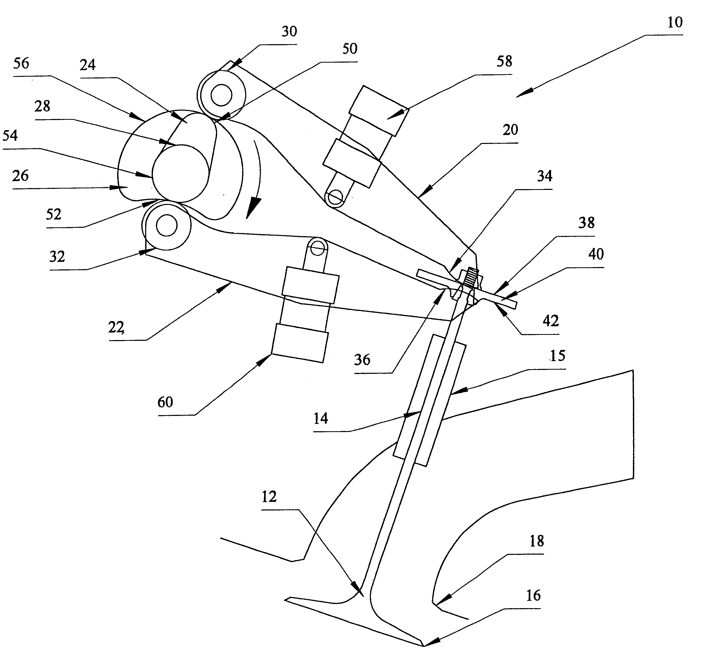
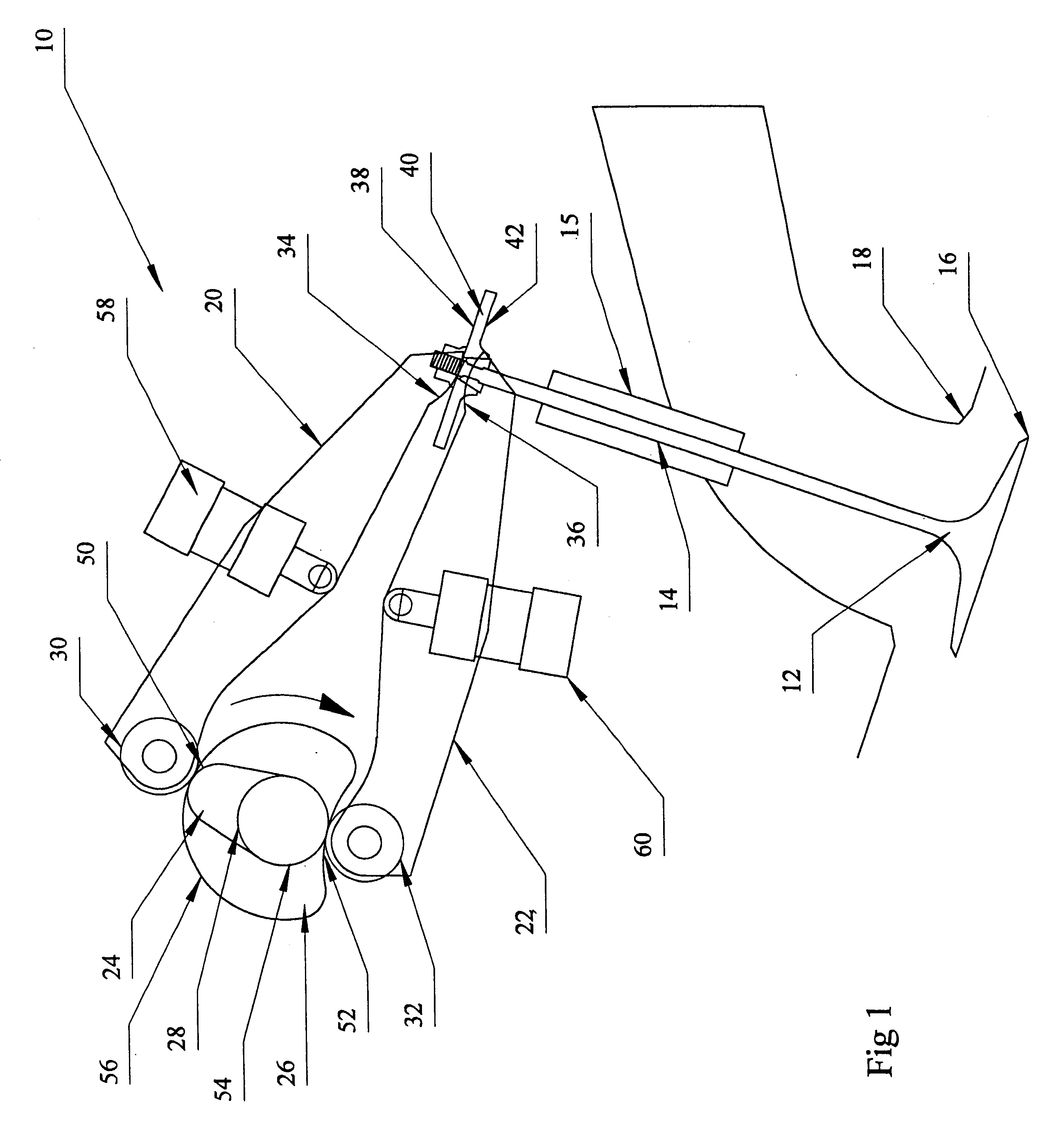
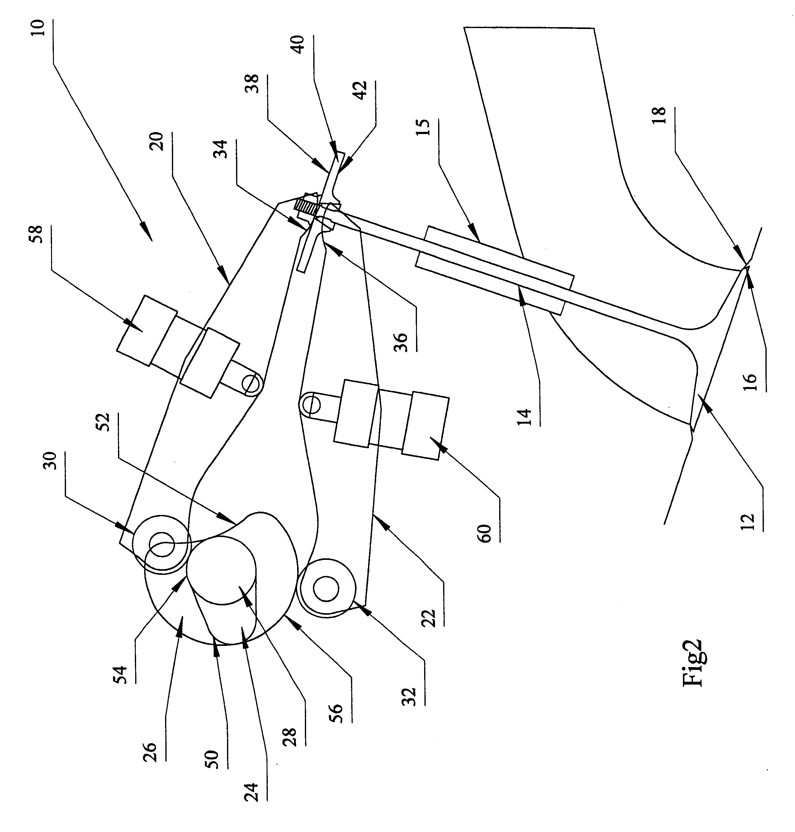
Referring now more particularly to FIGS. 1 and 2 of the drawings, there is shown an illustrative embodiment of a poppet valve system 10 for an internal combustion engine constructed in accordance with the present invention. The illustrated poppet valve 12, which as will be appreciated can be either an inlet valve or an exhaust valve, includes a valve stem 14 and a valve head 16 which is movable between a closed position in which it engages a valve seat 18 and an open position. In a known manner, the valve stem is supported for axial movement via a valve guide 15 so as to move the valve head 16 between its open and closed positions.

In accordance with an important aspect of the present invention, to enable higher valve actuation speeds, the poppet valve system 10 of the present invention does not include a valve spring. With conventional poppet valve systems, the force necessary to maintain the valve train components in contact dictates the spring stiffness required. Therefore, with s...


PUM


Abstract

A springless poppet valve system is provided. The system includes a poppet valve movable between an open position and a closed position. The system includes an open cam and a close cam. An open rocker arm is provided which engages the open cam. The open rocker arm is operatively connected to the poppet valve so as to move the valve from the closed position to the open position. A close rocker arm is provided which engages the close cam. The close rocker arm is operatively connected to the poppet valve so as to move the valve from the open position to the close position. An open hydraulic lifter is pivotally connected to the open rocker arm. A close hydraulic lifter is pivotally connected to the close rocker arm.

Description

The present invention relates generally to the valve train of an internal combustion engine and, more particularly, to a springless poppet valve system.Conventional poppet valve systems used in four-stroke internal combustion engines are typically biased to a closed position using a spring. The valve is moved to an open position against the force of the spring by a cam or cam-actuated rocker arm. On the open stroke of the valve, the cam or rocker arm also must move the valve counter to the momentum of the valve such that the open force required is effectively doubled. These conventional poppet valve systems, however, are limited with regard to speed at which the valves can be actuated. As will be appreciated, the limit on the valve actuation speed, in turn, limits the rate at which the engine can turn (i.e., engine rpm). As engine torque and speed dictate engine power, limits on the engine rpm constrain the power of an engine.In particular, increasing the actuation speed of the valv...

Claims


Application Information

Patent Timeline
Patent Type & Authority Patents(United States)
IPC IPC(8): F01L1/00F01L1/30
CPCF01L1/30
Inventor PALUMBO, CHRIS
Owner PALUMBO CHRIS
Why Eureka
Try Eureka