Direct chill casting mold system

a technology of direct chilling and molds, applied in the field of metals, can solve the problems of not being able to quickly change the feed of materials, not being able to have molten materials, and not being able to achieve rapid change of material feed, etc., and no researcher has put together a dynamic model of heat transfer in direct chill casting without making certain assumptions and accepting many approximations

Inactive Publication Date: 2002-12-10
TILAK RAVINDRA V
View PDF23 Cites 30 Cited by
  • Summary
  • Abstract
  • Description
  • Claims
  • Application Information

AI Technical Summary

Problems solved by technology

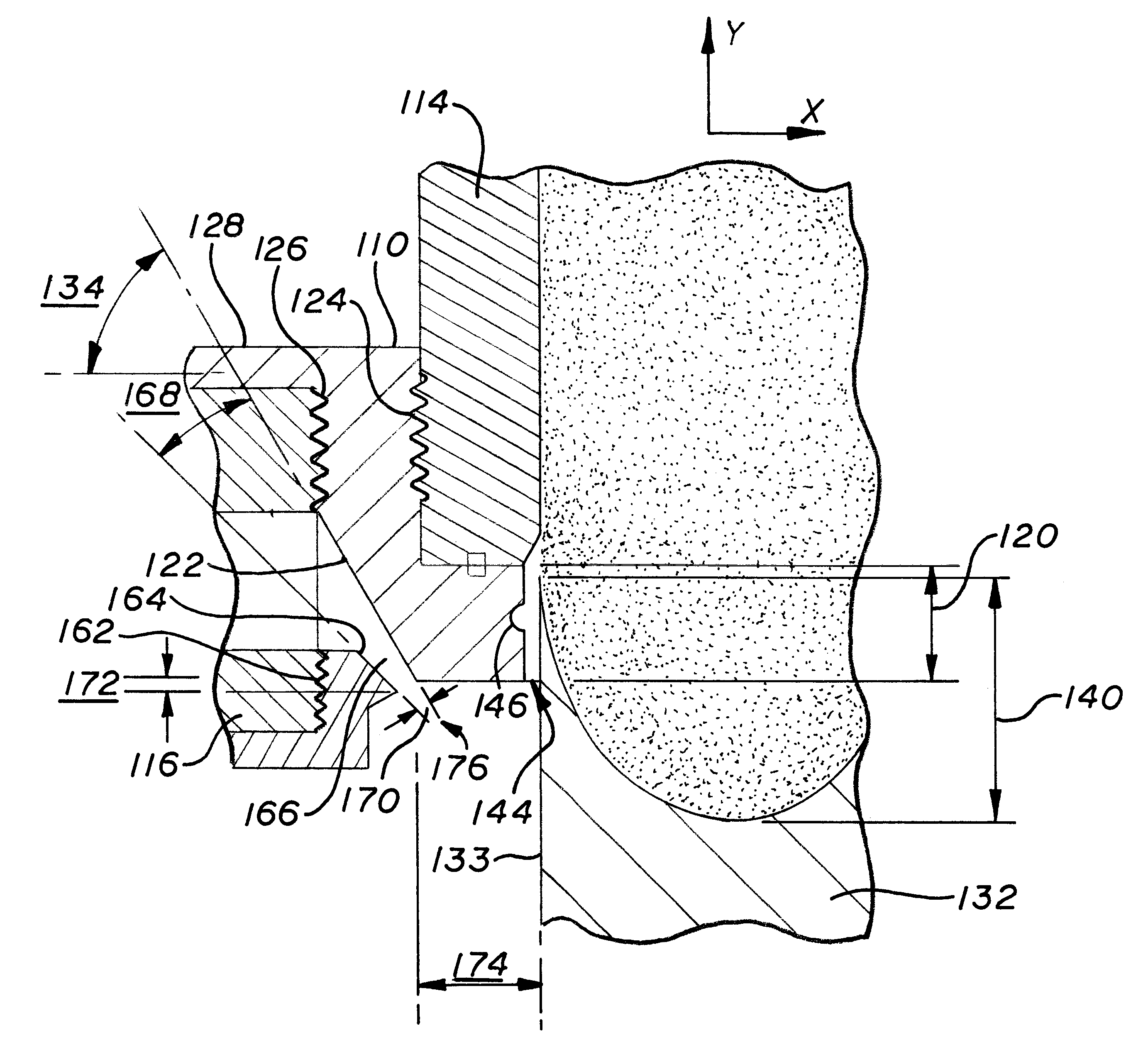
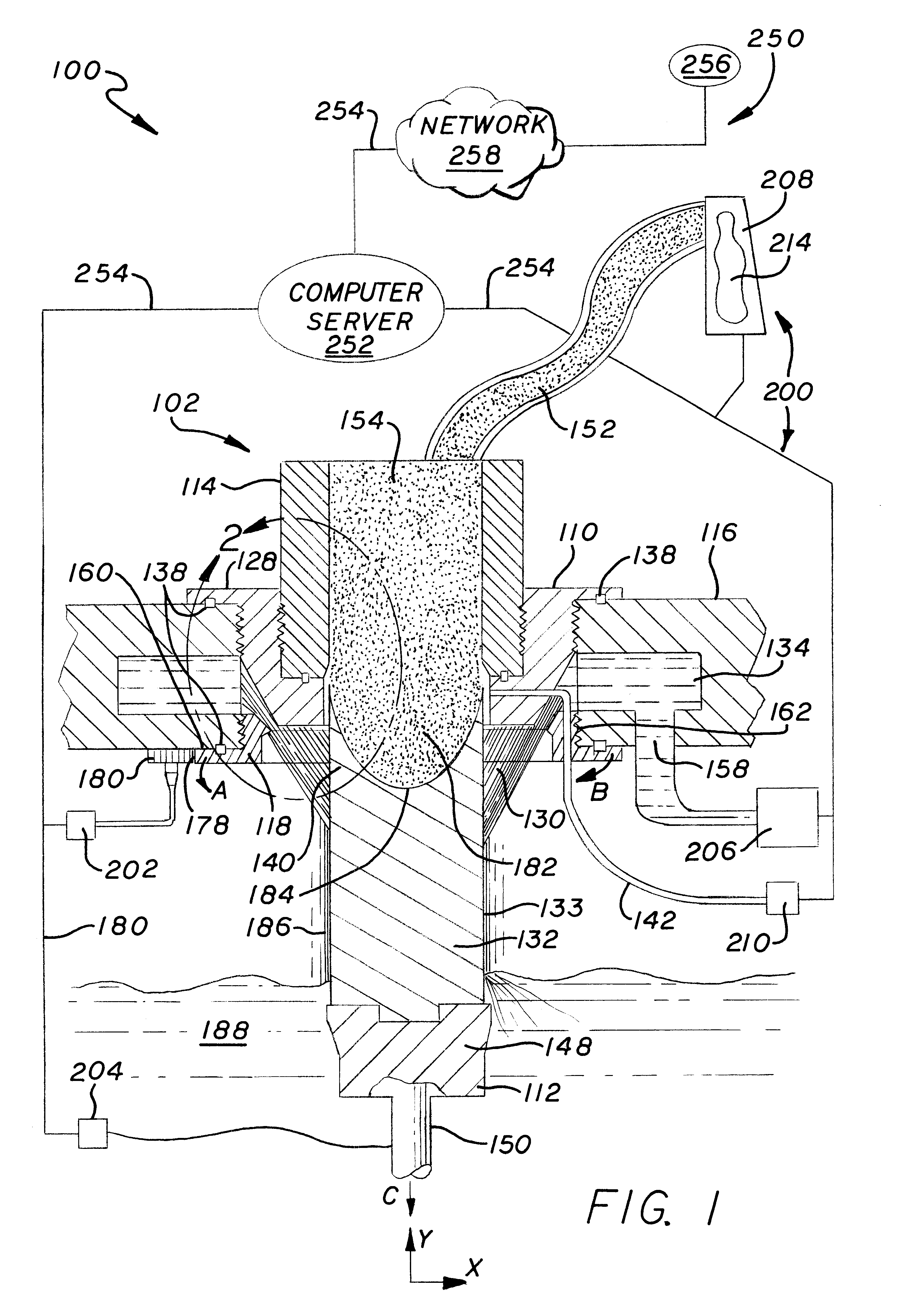
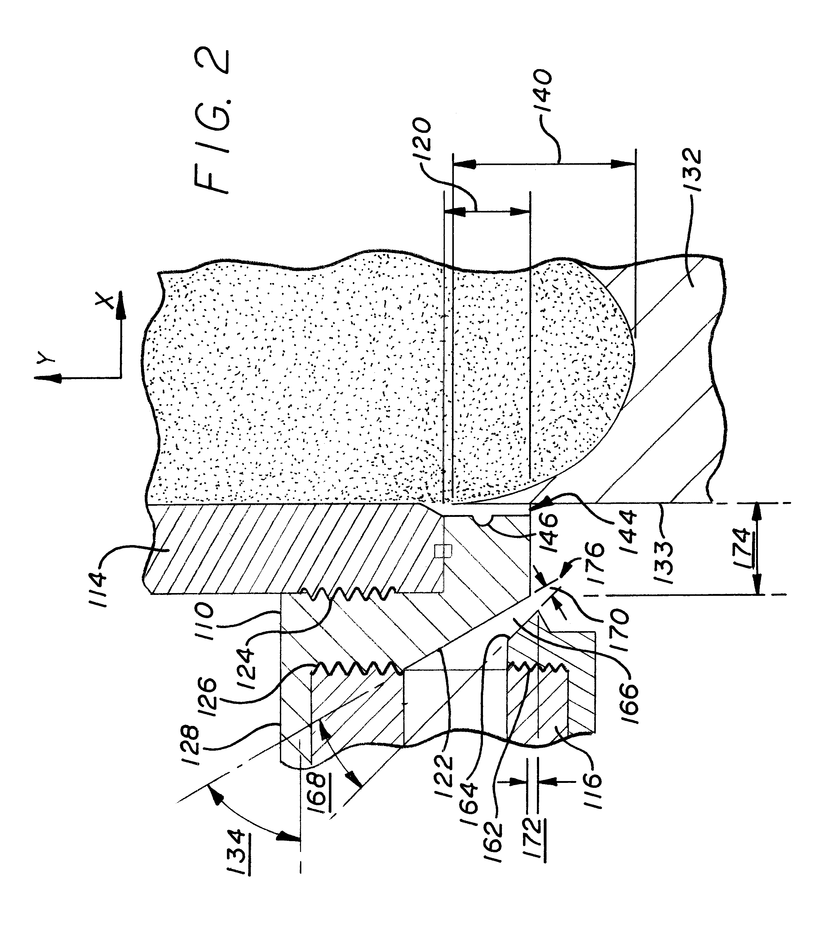
It may be undesirable to have molten material 152 cooling prior to reaching heat absorbing ring 120.
In a practical environment of continuous casting, it may not be possible to change quickly the material feed level inside the feeder tube 114 and the material temperature since these variables may have high inertia, where the high inertia may be due in part to the variables being maintained by the continuous supply of molten material from a material melting furnace.
Although heat transfer from hot materials to flowing cooling media has been researched for over a century and heat transfer in direct chill casting for over half a century, no researcher has put together a dynamic model of heat transfer in direct chill casting without making certain assumptions and accepting many approximations.
A holistic approach has been lacking.
However, these models are not sufficient for predicting the casting behavior and the metallurgical structure of the cast material.

Method used


Image

  • Direct chill casting mold system
  • Direct chill casting mold system
  • Direct chill casting mold system

Examples


example 1 observations

stings could be conducted without encountering any problem related to dimensional stability of the mold system. The mold system remained rigid and showed excellent resistance to thermal fatigue resulting from start and completion of the casting cycle. No leakage was observed in the molten metal, coolant media or lubrication line flow paths over repeated uses of the mold package. No steam was observed in the immediate vicinity of water impingement location on the billet and downstream of that point under the mold table or above the mold table. The surface of the billet was smooth and qualifying for the required industry standard set for direct extrusion application. The metallurgical structure of the billet exhibited 75 microns as grain size and around 42 microns as cell size (interdendritic spacing) at the center of the billet. The sub-surface liquation band varied in depth ranging from 0.015 to 0.060 inches with average close to 0.030 inches. The casting speeds that could be attain...

example 2

B. Example 2

Set Up: Conditions mentioned in example 1 were maintained except recycled water was used as cooling media. The recycled water typically had the following chemistry:

i) Total dissolved solids of 1,200 milligrams per liter (as compound to 250 milligrams for city water);

ii) Total suspended solids which generated about two pounds per square inch (psi) pressure difference across the in-line filter during the course of the casting (mesh opening 0.064 inches); and

iii) Total oil and grease content of 60 milligrams per liter.

example 2 observations

esult of using recycled water, no deleterious effect was observed on the functioning of the mold system. No change was required in the casting practice of the billets, the same thresholds of casting speeds could be maintained with recycled water as with direct city water. The metallurgical structure of the billet did not indicate any difference from that observed in example 1.


PUM

PropertyMeasurementUnit
angleaaaaaaaaaa
angleaaaaaaaaaa
angleaaaaaaaaaa

Abstract

An embodiment includes a casting mold. The casting mold may include a mold body having a direction surface and a coolant box coupled to the mold body. The casting mold further may include a coolant ring having a regulation surface where the coolant ring may be coupled to the coolant box so as to bring the regulation surface and the direction surface together to form a nozzle. The casting mold further may include a mold starting head.

Description

1. Field of the InventionThe invention includes the metal founding process of continuously and semi-continuously shaping liquid metal against a forming surface. More particularly, the invention includes direct chill casting of a billet by applying liquid coolant directly to the billet product.2. Background InformationFounding includes making objects by introducing molten material into a mold where the material solidifies as heat is removed from the material. Slip or continuous casting may be a process whereby molten metal is solidified by gravity feeding the molten metal through a heat absorbing ring. A starting head, having a base mounted to a hydraulic ram, forms an unattached bottom to the heat absorbing ring. The heat absorbing ring and the starting head comprise the basic elements of a slip mold.When the molten metal fills the mold and begins to solidify, the starting head may be lowered at a controlled rate. Solidified metal may exit the heat absorbing ring to form a billet. R...

Claims


Application Information

Patent Timeline
Patent Type & Authority Patents(United States)
IPC IPC(8): B22D11/049
CPCB22D11/049
Inventor TILAK, RAVINDRA V.
Owner TILAK RAVINDRA V
Why Eureka
Try Eureka