In the hard macro array in accordance with the present invention, the base material, on which the test substance-containing spots are formed, is the film-shaped hard porous body. Therefore, the advantages over the conventional macro arrays, in which
polymer types of porous membranes are utilized as the base materials, can be obtained in that the film-shaped hard porous body are not apt to suffer from bending and creasing as in the cases of the
polymer types of porous membranes having a markedly high softness. Therefore, the operator need not pay close attention to the prevention of bending and creasing of the film-shaped hard porous body and is capable of more easily
processing the hard macro array in accordance with the present invention than in the conventional macro arrays.
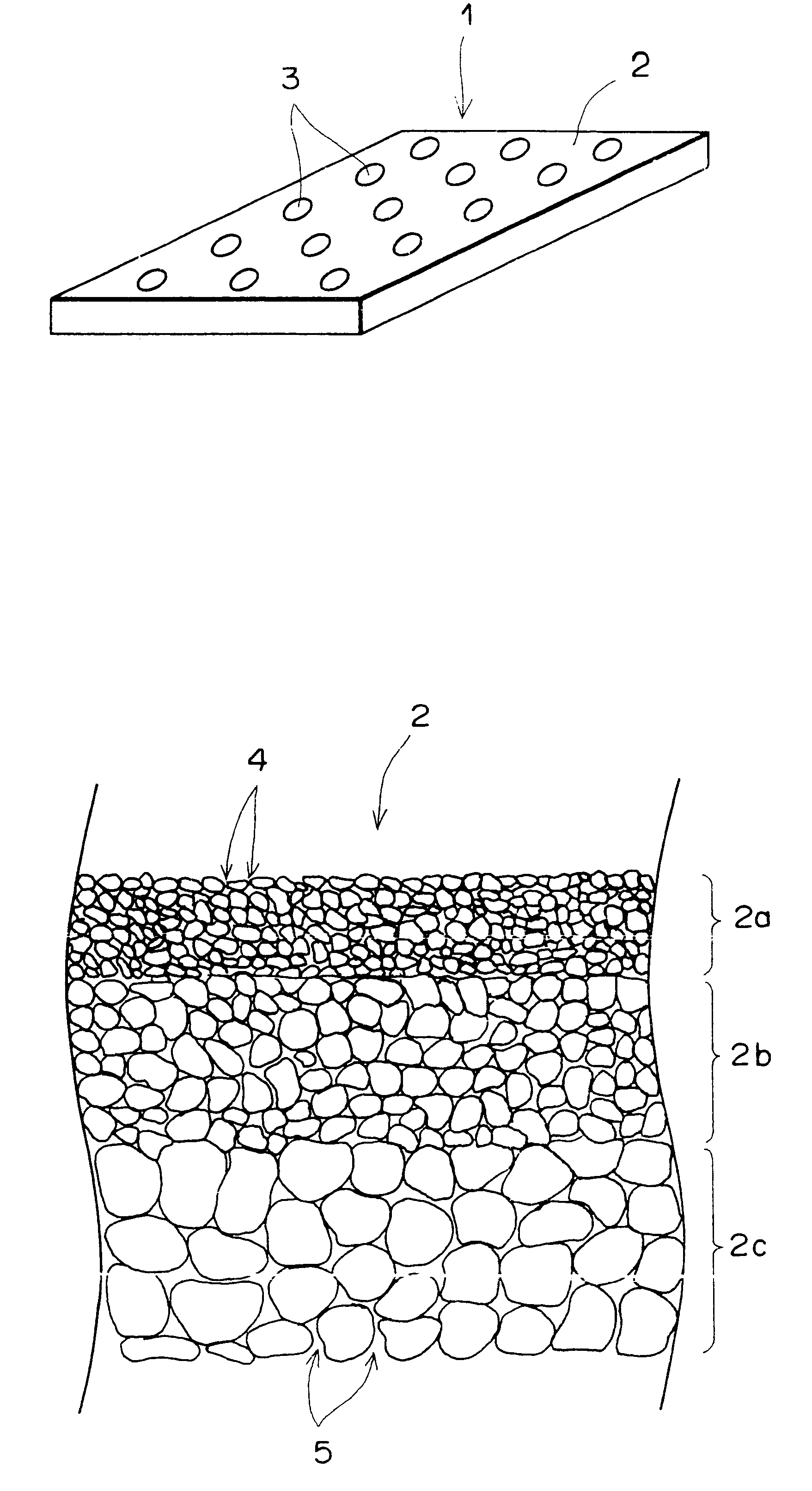
Also, with the hard macro array in accordance with the present invention, wherein the base material is constituted of the film-shaped hard porous body, when the test substance-containing sample is applied drop-wise (i.e., spotted) onto the film-shaped hard porous body, part of the test substance-containing sample is capable of permeating to the interior of the pore. Therefore, the test substance-containing sample having been spotted can be restricted from diffusing horizontally on the surface of the base material (i.e., the film-shaped hard porous body). As a result, the
diameter of the spot formed on the surface of the base material can be kept small. Accordingly, with the hard macro array in accordance with the present invention, the comparatively small spots can be arrayed at a
high density.
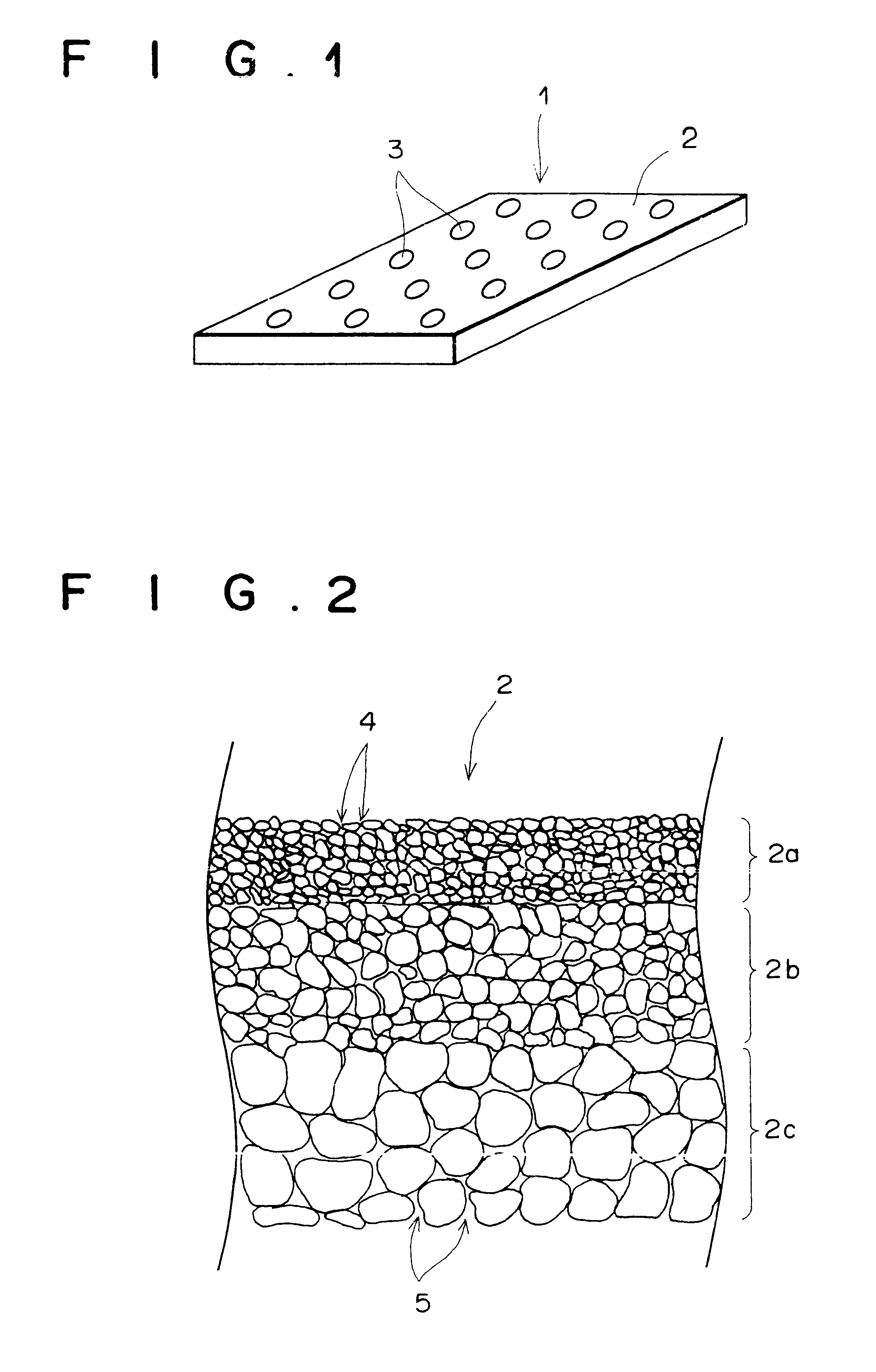
In the hard macro array in accordance with the present invention, the film-shaped hard porous body should preferably be constituted of a
surface layer region, which is provided with through-pores having a comparatively small mean pore
diameter, and a base layer region, which is provided with through-pores having a comparatively large mean pore
diameter. The term "
surface layer region" as used herein means the surface layer region of the base material containing the surface on which the spots are formed and arrayed. The term "base layer region" as used herein means the layer region, which is adjacent to the surface layer region with respect to the direction of the film thickness of the film-shaped hard porous body. With the hard macro array in accordance with the present invention, wherein the film-shaped hard porous body is constituted of the surface layer region, which is provided with the through-pores having a comparatively small mean pore diameter, and the base layer region, which is provided with through-pores having the comparatively large mean pore diameter, the test substance applied onto the surface of the surface layer region is apt to remain on the surface of the surface layer region due to the comparatively small pore diameters of the pores in the surface layer region. Also, a
solvent, such as water, which is contained in the applied spot and enters into the pores in the surface layer region, is capable of being quickly introduced toward the bottom surface side of the film-shaped hard porous body via the pores larger than the pores of the surface layer region. Therefore, the formation of the spots can be performed efficiently.
Further, in the hard macro array in accordance with the present invention, a surface of the film-shaped hard porous body, on which surface the spots are to be arrayed, should preferably be coated with an auxiliary substance for promoting fixation of the test substances to the surface of the film-shaped hard porous body. With the hard macro array in accordance with the present invention, wherein the surface of the film-shaped hard porous body is coated with the auxiliary substance, the efficiency, with which the test substances are fixed to the surface of the inorganic type of film-shaped hard porous body, can be enhanced.
The hard macro array in accordance with the present invention has a higher
hardness than the
hardness of the conventional macro arrays, in which polymeric organic membranes are employed as the base materials. Therefore, the hard macro array in accordance with the present invention is easy to process, and careless bending, creasing, or the like, can be prevented from occurring. Also, with the hard macro array in accordance with the present invention, the operator is capable of being released from feeling of tension and stress at the time of the operation for hybridization, autoradiography, or the like. Further, with the hard macro array in accordance with the present invention, operation characteristics can be enhanced, and therefore the
processing, such as hybridization or autoradiography, is capable of being performed efficiently and smoothly.

