VLIW processor for exchanging and inputting sub-instructions to containers, and code compression device and method for compressing program code

a processor and container technology, applied in the field of vliw processors, can solve the problems of low code density, the limitation of the current lsi (large-scale integration) manufacturing technique in achieving higher device speed,

Inactive Publication Date: 2002-12-24
MITSUBISHI ELECTRIC CORP
View PDF8 Cites 29 Cited by
  • Summary
  • Abstract
  • Description
  • Claims
  • Application Information

AI Technical Summary

Problems solved by technology

However, the current LSI (Large Scale Integration) manufacturing technique has a limit in attaining higher device speed.
Thus, a nop

Method used


Image

  • VLIW processor for exchanging and inputting sub-instructions to containers, and code compression device and method for compressing program code
  • VLIW processor for exchanging and inputting sub-instructions to containers, and code compression device and method for compressing program code
  • VLIW processor for exchanging and inputting sub-instructions to containers, and code compression device and method for compressing program code

Examples


code example 2

instruction sequence for instruction sequence for code number left sub-instructions right sub-instructions 1 store R0 .fwdarw. mem (200) :sub R4, R5 .fwdarw. R6 2 load mem (100) .fwdarw. R1 :add R1, R2 .fwdarw. R3

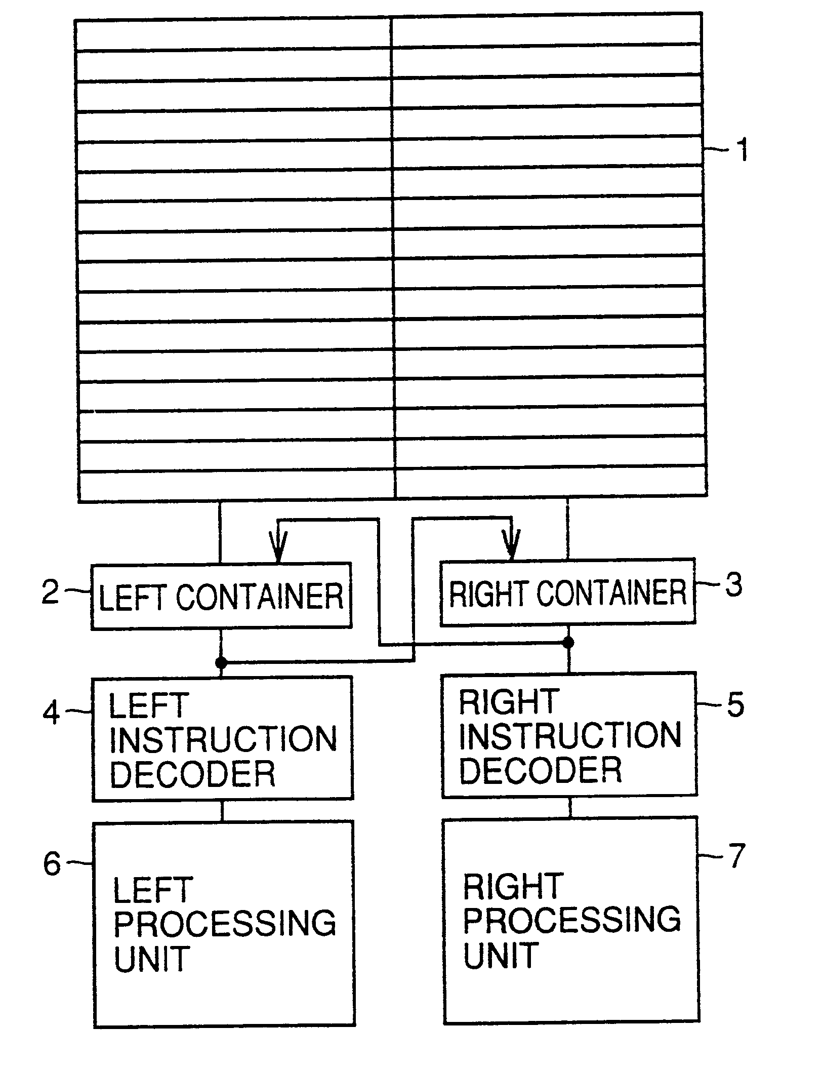
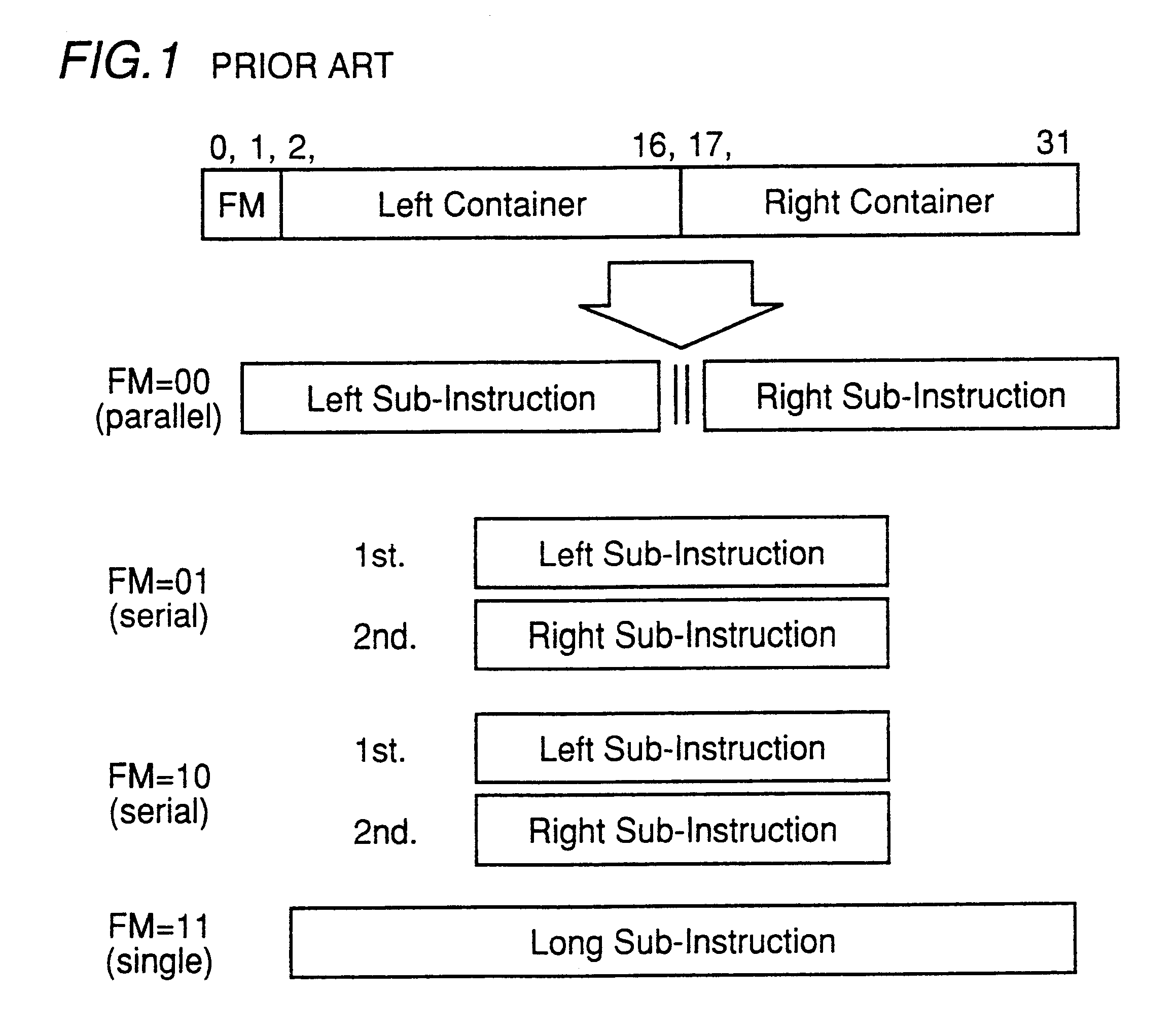
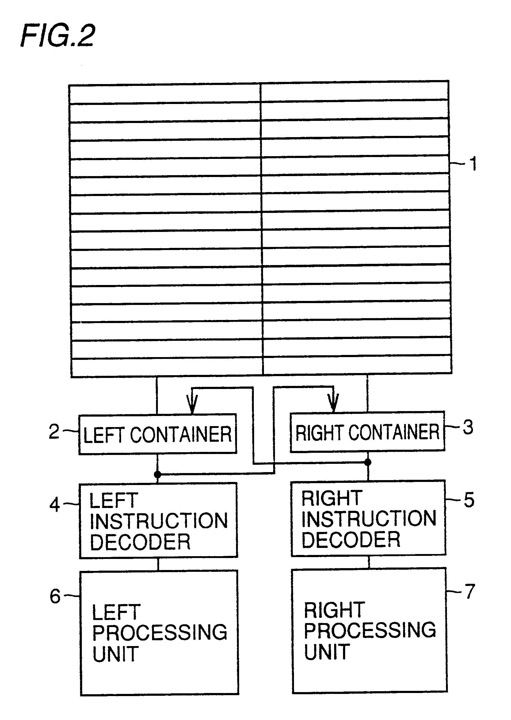
For this operation, FM (Format-Specifying) bits are assigned to lower order two bits of the 32-bit VLIW instruction, and the instruction is executed by processor in the following manner according to the FM bit pattern. (1) FM=00: simultaneously execute two sub-instructions (2) FM=01: execute the left sub-instruction and then execute the right sub-instruction (3) FM=10: execute the right sub-instruction and then execute the left sub-instruction (4) FM=11: execute two sub-instructions by regarding the two sub-instructions as one long instruction

Since the operation mode in the case of FM=11 is irrelevant to the present invention, it will not be described in detail. FIG. 1 schematically shows relations between FM bits and instruction execution.

Code example 1 is described as cod...

code example 3

instruction sequence for instruction sequence for code number FM left sub-instructions right sub-instructions 1 00 store R0 .fwdarw. mem (200) :sub R4, R5 .fwdarw. R6 2 01 load mem (100) .fwdarw. R1 :add R1, R2 .fwdarw. R3

In executing code example 3, a processor executes instructions as shown in execution sequence example 1.

example 1

Execution Sequence Example 1

instruction sequence for instruction sequence for step number left sub-instructions right sub-instructions 1 store R0 .fwdarw. mem (200) :sub R4, R5 .fwdarw. R6 2 load mem (100) .fwdarw. R1 : 2' :add R1, R2 .fwdarw. R3

In the 2nd cycle, an arithmetic unit corresponding to the add instruction assumes the non-operation state and carries out substantially the same operation as execution of the nop instruction. In the 2'nd cycle, an arithmetic unit corresponding to the load instruction assumes the non operation state and carries out substantially the same operation as execution of the nop instruction. Therefore, execution sequence example 1 is equivalent to execution of code example 1. Since instructions are stored in an instruction memory in the format of code example 3, they are compressed to 2 / 3 times the capacity compared with code example 1.

In the conventional VLIW processor above, the order of describing sub-instructions can be determined more freely and...


PUM


Abstract

A VLIW processor includes a plurality of containers holding a plurality of sub-instructions in a VLIW instruction, an exchanging portion exchanging the plurality of sub-instructions held in the plurality of containers and inputting the instructions to the plurality of containers, a plurality of decoders decoding the sub-instructions held in the plurality of containers, and a plurality of processing units executing the sub-instructions decoded by the plurality of decoders. Since the exchanging portion exchanges a plurality of sub-instructions held in the plurality of containers and inputs the instructions to the plurality of containers, a compressed code can be executed in such an execution sequence that is taken prior to compression.

Description

1. Field of the InventionThe present invention relates to VLIW (Very Long Instruction Word) processors and more particularly to a VLIW processor which executes a compressed program code, a code compression device which compresses a program code, a code compression method, and a medium on which a code compression program is recorded.2. Description of the Background ArtThere have been increasing demands for improved processor performance in various fields such as multimedia processing and high resolution image processing. However, the current LSI (Large Scale Integration) manufacturing technique has a limit in attaining higher device speed. Therefore, VLIW processors have been drawing attention and actively researched and developed.The VLIW processor which contains a plurality of processing units aims to improve the performance of a program-controlled processor by executing a plurality of instructions in the same cycle and thus increasing parallelism. In the VLIW processor, a processi...

Claims


Application Information

Patent Timeline
IPC IPC(8): G06F9/30G06F9/38G06F9/45
CPCG06F9/30178G06F9/3853G06F9/3822
Inventor SUZUKI, HIROAKI
Owner MITSUBISHI ELECTRIC CORP
Why Eureka
Try Eureka