
Method for additive adhesion force particle analysis and apparatus thereof

Inactive Publication Date: 2003-01-21
XEROX CORP
View PDF20 Cites 24 Cited by
  • Summary
  • Abstract
  • Description
  • Claims
  • Application Information

AI Technical Summary

Problems solved by technology

However, with advances in modem analytical instrumentation the separation step may for certain target analytes or for certain system configurations, the need for a separation or separations of particulates from the liquid phase may be obviated and unnecessary.
Historically ICP has been conducted on solutions or solubilized analytes wherein difficult to solubilize materials can be dissolved with strongly corrosive or caustic reagents, and which reagents are expensive to handle and to dispose of and present significant safety concerns and challenges.
Generally, ICP analysis results obtained from suspensions are not very reproducible.

Method used


Image

  • Method for additive adhesion force particle analysis and apparatus thereof
  • Method for additive adhesion force particle analysis and apparatus thereof
  • Method for additive adhesion force particle analysis and apparatus thereof

Examples


example i

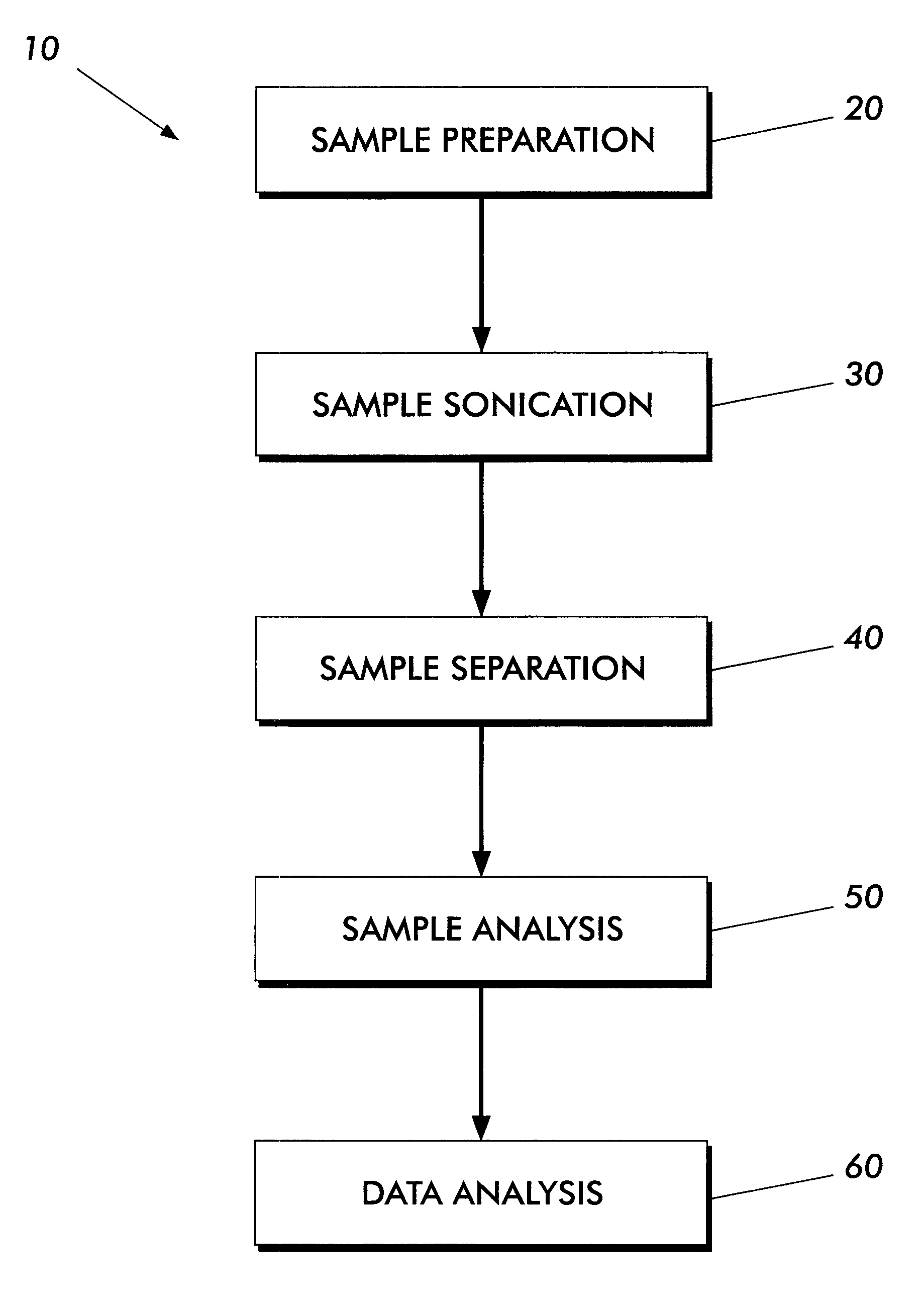
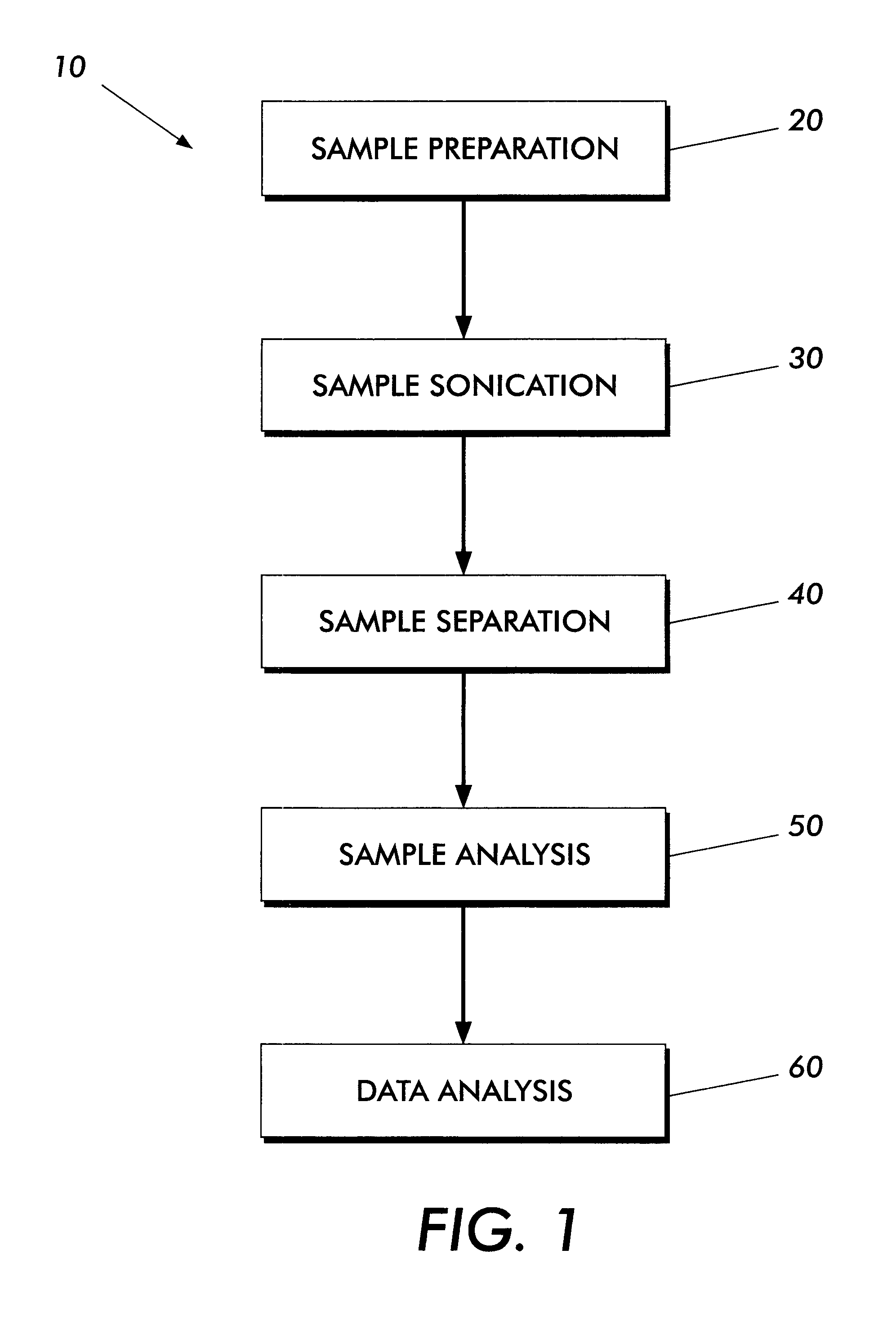
SAMPLE PREPARATION

A 0.5 gram sample of surface treated toner was weighed into a centrifuge tube. To the tube was added 15 mL of Triton-X100 surfactant, commercially available from Rohm & Haas, and deionized water to afford a surfactant in water at about 0.4 weight percent. The mixture was suspended with a vortex mixer for set period of about ten to about sixty seconds and then sonicated for a set period of time and a set or predetermined, that is programmed, amount of sonic energy.


PUM


Abstract

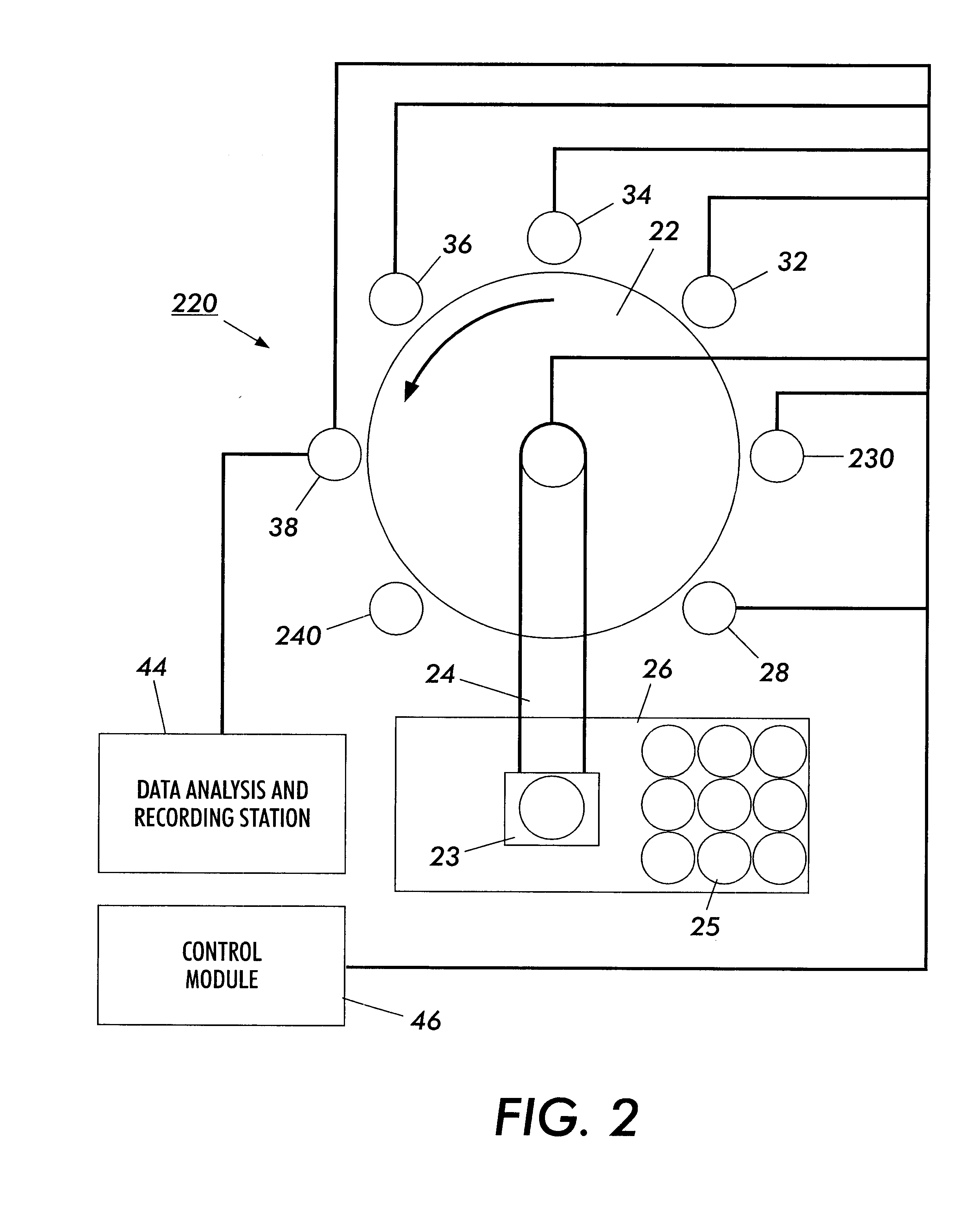
A method including: sonicating a liquid suspension of first particles; and analyzing the liquid phase for second particles. An apparatus including: a sonicator adapted to sonicate a liquid suspension of first particles; and a first analyzer adapted to analyze the sonicated liquid phase for second particles. The method and apparatus can be used to analyze the adhesion force relationships between the main or host first particles and guest or surface additive second particles.

Description

The present invention is generally directed to a method and apparatus for measuring the adhesive force of smaller surface additive particles to larger particles. More specifically the present invention is directed to a multi-horn ultrasonic agitator system which enables precise control of ultrasonic energy output from the horns and which system permits the analysis of, for example, liquid and solid phases, and small surface additive constituents(guest particles) residing on larger sized particulates(host particles). The present invention also provides automated robotic control and sample handling for efficient and automatic operation. The present invention provides methods and apparatuses for host and guest particle separation or host and guest particle extraction. The present invention provides an analytical tool to characterize the amount of guest surface additive(s) on and off the host or main particles, such as toners versus the amount of surface additive irrevocably impacted on...

Claims


Application Information

Patent Timeline
IPC IPC(8): G01N15/04G01N35/00G01N15/00
CPCG01N15/042G01N2291/02416G01N2035/00554G01N2015/0053
Inventor DELUCA, ALLEN F.LINCOLN, TIMOTHY L.LE, HON H.DEMAY, CHRISTINE L.MURRAY, ERICALLEN, DAVID A.GANGULY, LEELA
Owner XEROX CORP
Learn More