
Auto-ignition combustion management in internal combustion engine

a technology of combustion management and internal combustion engine, which is applied in the direction of machines/engines, output power, electric control, etc., can solve the problems of increasing engine speed, unacceptably high vibration and noise, and extremely low nox emission produced in controlled auto-ignition combustion

Inactive Publication Date: 2003-01-21
NISSAN MOTOR CO LTD
View PDF16 Cites 45 Cited by
  • Summary
  • Abstract
  • Description
  • Claims
  • Application Information

AI Technical Summary

Benefits of technology

The system enables stable auto-ignition combustion of gasoline fuel across varying conditions, improving fuel economy, reducing noise and vibration, and maintaining low NOx emissions by adjusting main combustion timing and period to optimize engine performance.

Problems solved by technology

NOx emission produced in controlled auto-ignition combustion is extremely low.
However, there is a limit to increasing load request because burning velocity increases rapidly to bring about a rapid increase in cylinder pressure during operation with high load, resulting in unacceptably high level of vibration and noise.
Besides, there is a limit to increasing engine speed because combustion is not completed within one cycle at high engine speeds, resulting in high emission of unburned gas.
However, applying this control strategy to a gasoline internal combustion engine does not provide satisfactory auto-ignition combustion of gasoline fuel.

Method used


Image

  • Auto-ignition combustion management in internal combustion engine
  • Auto-ignition combustion management in internal combustion engine
  • Auto-ignition combustion management in internal combustion engine

Examples


Embodiment Construction

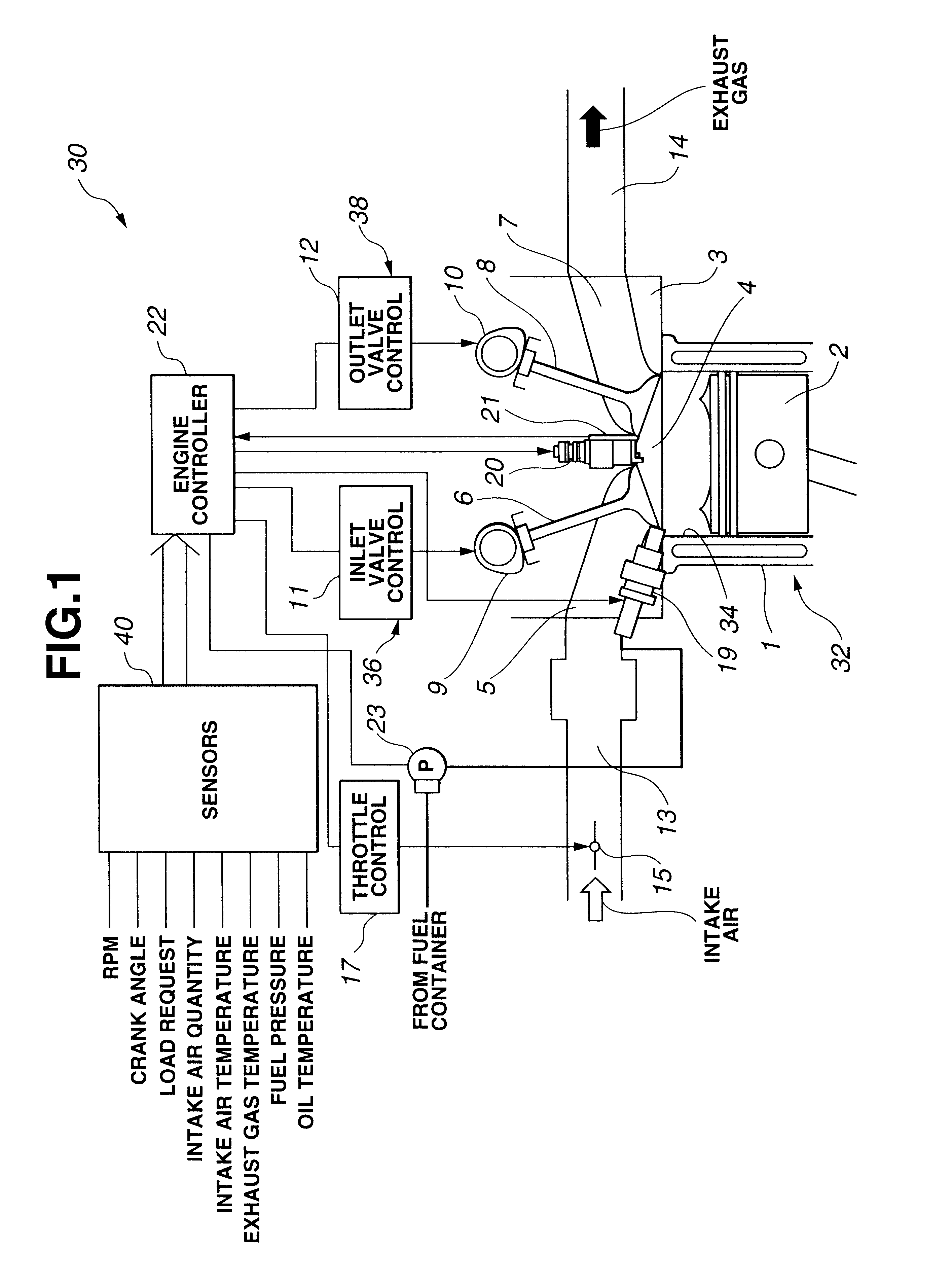
FIG. 1 provides a block diagram of a system or method for auto-ignition of gasoline fuel in an internal combustion engine. System 30 includes an internal combustion engine, indicated generally by reference numeral 32, in communication with an engine controller 22.

In FIG. 1, the area of a combustion chamber of engine 32 is shown. Engine 32 has a cylinder block 1 and a cylinder head 3. Cylinder block 1 has at least one cylinder 34 with a piston 2 reciprocating therein to define a combustion chamber 4 in cooperation with cylinder head 3. Combustion chamber 4 is shown communicating within an intake conduit 13 and an exhaust conduit 14 via intake and exhaust ports 5 and 7 in a known manner.

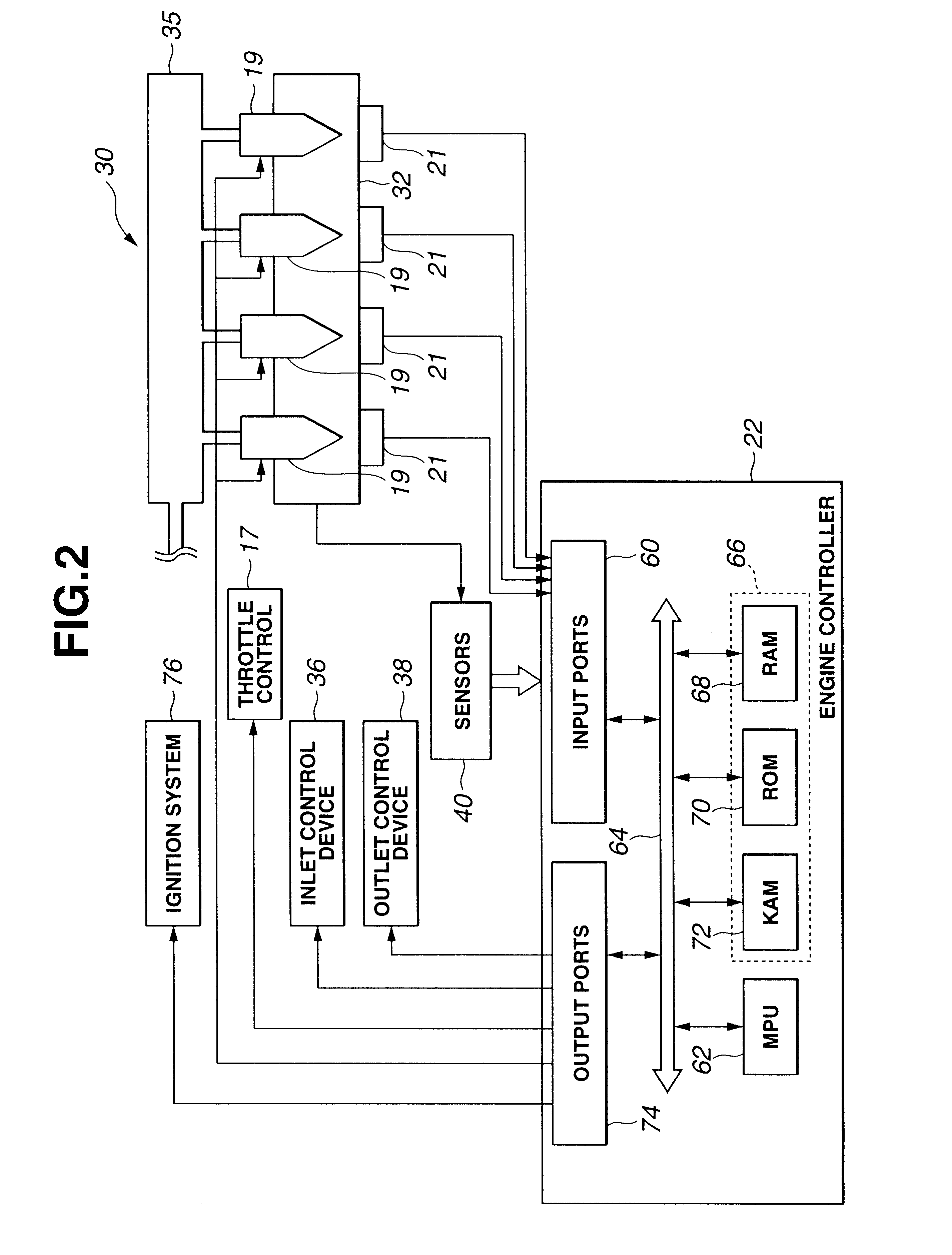
Referring also to FIG. 2, engine 32 is an internal combustion engine, such as a four, six or eight-cylinder gasoline engine. Fuel injectors 19 are shown receiving pressurized fuel from a supply 35 that is connected to a high-pressure pump 23 as shown in FIG. 1. Alternatively, embodiments of the present...


PUM


Abstract

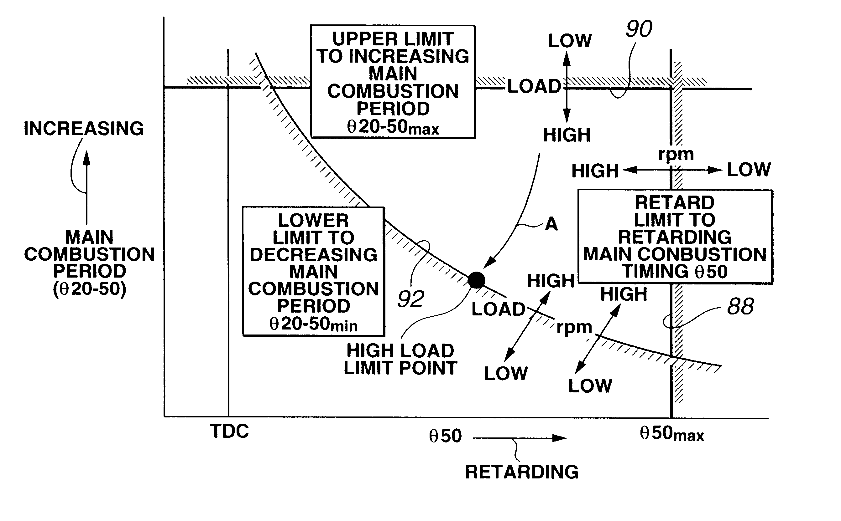
An internal combustion engine is operated on auto-ignition combustion of fuel with low cetane number like gasoline. The engine has at least one cylinder and a reciprocating piston in the cylinder to define a combustion chamber. Combustion event in the cylinder is expressed in terms of two variables. They are main combustion timing (theta50) and a main combustion period (theta20-50). The main combustion timing (theta50) represents a crank position when mass burnt rate is 50 percent. The main combustion period (theta20-50) represents a period from a crank position when mass burnt is 20 percent to a crank position when mass burnt is 50 percent. Controlled parameters governing main combustion are varied to adjust the main combustion timing on an advance side of a retard limit (theta50 max) and to adjust the main combustion period within a range between an upper limit (theta20-50 max) and a lower limit (theta20-50 min).

Description

The present invention relates to an internal combustion engine, which can be operated on auto-ignition combustion of fuel with low cetane number like gasoline, and more particularly to a system and method for auto-ignition combustion management in an internal combustion engine.DESCRIPTION OF RELATED ARTWhen certain conditions are met within a charge of lean air / fuel mixture during low load operation, auto-ignition can occur wherein bulk combustion takes place initiated simultaneously from many ignition sites within the charge, resulting in very stable power output, very clean combustion and high thermal efficiency. NOx emission produced in controlled auto-ignition combustion is extremely low. In controlled auto-ignition combustion where the combustion is uniformly distributed throughout the charge from many ignition sites, the burnt gas temperature is substantially homogeneous with much lower local temperature values resulting in very low NOx emission.Auto-ignition combustion at low...

Claims


Application Information

Patent Timeline
Patent Type & Authority Patents(United States)
IPC IPC(8): F02D37/00F02D35/02F02D37/02F02B1/12F02D41/30F02D41/40F02B1/00F02B1/04F02B75/12F02B75/00F02D13/02F02B11/00F02D41/02F02D41/04
CPCF02B1/04F02D13/0215F02D13/0265F02D35/023F02D35/028F02D37/02F02D41/3035F02D41/402F02B1/12F02D2200/025F02B2075/125F02B2275/18F02D35/027F02D41/006F02D2041/001F02D2041/389Y02T10/18Y02T10/44F02D41/0057F02D41/3041F02D41/3047Y02T10/12Y02T10/40
Inventor MIYAKUBO, HIROSHIIIYAMA, AKIHIROTANIYAMA, TSUYOSHIYOSHIZAWA, KOUDAI
Owner NISSAN MOTOR CO LTD
Learn More