Screens for vibratory separators

a technology of vibratory separator and screen, which is applied in the direction of filtration separation, separation process, and well accessories, etc., can solve the problems of lcm material difficulty in combination, weight, viscosity and gel problems in the mud, and increase the wear of mud pumps and other mechanical equipment used for drilling, so as to facilitate the passage of such material through the screen assembly

Inactive Publication Date: 2003-01-28
VARCO I P INC
View PDF7 Cites 96 Cited by
  • Summary
  • Abstract
  • Description
  • Claims
  • Application Information

AI Technical Summary

Benefits of technology

Such methods in which the resident time in a screen assembly of material that can swell is reduced and the passage of such material through the screen assembly is facilitated;

Problems solved by technology

If drilled solids are not removed from the mud used during the drilling operation, recirculation of the drilled solids can create weight, viscosity, and gel problems in the mud, as well as increasing wear on mud pumps and other mechanical equipment used for drilling.
The frame of the vibrating screen is resiliently suspended or mounted upon a support and is caused to vibrate by a vibrating mechanism, e.g. an unbalanced weight on a rotating shaft connected to the frame.
Whether fractures induced by excessive mud pressure are parallel to the axis of the borehole (vertical) or perpendicular to the axis of the borehole (horizontal) is a subject of some controversy.
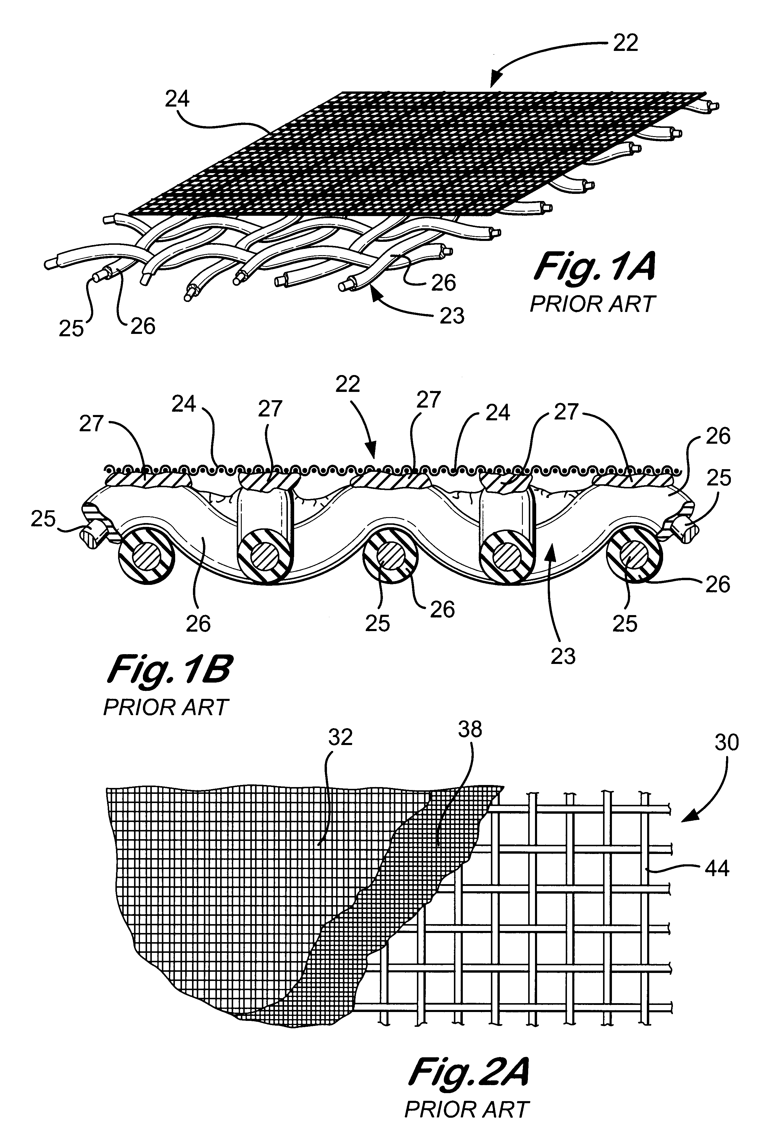
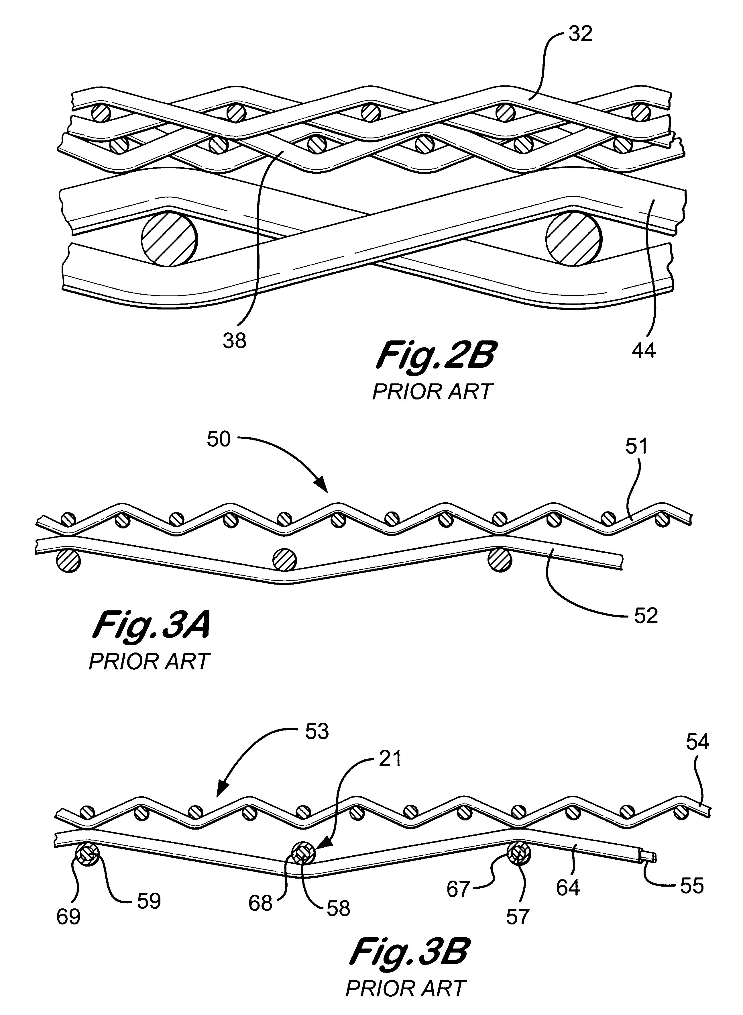
Certain of these screen combinations have difficulty in handling LCM material and the material often blinds these screens.
Typical known shale shaker screens or screen assemblies with square mesh openings often are clogged when attempts are made to separate lost circulation materials from a mixture of them with fluid that has been pumped down a wellbore.
In certain particular circumstances there have been problems with commercially available ULTRA-SEAL lost circulation material that has fibrous material in it.

Method used


Image

  • Screens for vibratory separators
  • Screens for vibratory separators
  • Screens for vibratory separators

Examples


Embodiment Construction

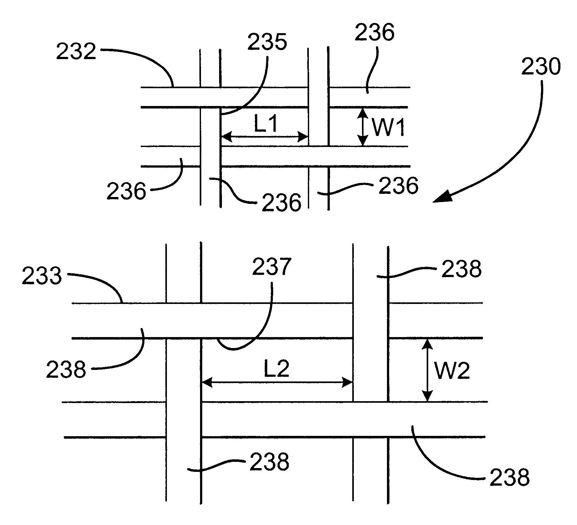
FIGS. 19A-19D show a screen assembly 210 according to the present invention which has a lowermost screen 212, a middle screen 214, and a top most screen 216. Any one of these three screens may be deleted. The screen assembly 210 may have any known side hookstrips; and / or any known screen support (indicated by numeral 213) including, but not limited to, support strips, frame and / or supporting perforated plate (each of which is not the legal equivalent of the others). Any two adjacent or all three screens may be bonded or connected together in any known manner.

The top screen 216 (see FIG. 19C) is woven of wires about 0.0012 to 0.0018 inches in diameter made of any suitable material, including but not limited to, metal, plastic, steel, and stainless steel, e.g. 304 or 316 SS. Any suitable known weave and weave pattern may be used. In the embodiment of FIG. 19C as viewed from above, the openings between intersecting wires are non-square and rectangular. In the embodiment shown the lengt...


PUM

PropertyMeasurementUnit
diameteraaaaaaaaaa
diameteraaaaaaaaaa
thicknessaaaaaaaaaa

Abstract

A screen assembly and methods for using it, the screen assembly including, in certain aspects, at least two layers of screening material one on top of the other and including at least a first layer over a second layer, each layer having screen mesh with rectangular openings as viewed from above, the first layer having first rectangular openings, and the second layer having second rectangular openings, each of the first rectangular openings having a first width and a first length, and each of the second rectangular openings having a second width and a second length, the ratio of the first length to the first width ranging between 1.55 and 2.00, the ratio of the second length to the second width ranging between 1.55 and 2.00, the ratio of the first length to the second width ranging between 0.95 and 1.05, and the lengths of the first rectangular openings are parallel to lengths of the second rectangular openings.

Description

1. Field of the InventionThis invention is directed to screens for use on a vibratory separator to treat fluid introduced to the vibratory separator; and, in certain particular aspects, to such screens for use on shale shakers; and other particular aspects to such screens for treating drilliing fluid with drilled cuttings therein.2. Description of Related ArtA wide variety of vibratory separators are used in various industries to separate components of material fed to the vibratory separator. Often the material is a slurry which includes liquid and solids entrained therein and it is desired to separate some, the majority of, or all of the solids from the liquid. One or more screens is typically mounted on the vibratory separator and the material to be treated is introduced onto the screen(s). Liquid, and perhaps some solids, flows through the screen and is collected and solids that do not flow through the screen move off the top of the screen. In other systems, solids of one size fl...

Claims


Application Information

Patent Timeline
Patent Type & Authority Patents(United States)
IPC IPC(8): B01D39/10B01D39/12B01D29/01B01D33/03B01D33/00B07B1/46
CPCB01D29/012B01D33/0093B01D33/0376B01D39/12B07B1/4663B07B1/4672B07B1/469B01D29/05
Inventor SCHULTE, DAVID L.ADAMS, THOMAS C.LARGENT, DAVID W.
Owner VARCO I P INC
Why Eureka
Try Eureka