Micro-electro-mechanical gyroscope

a micro-electromechanical and gyroscope technology, applied in the field of gyroscopes, can solve the problems of large effort required to design and fabricate the vibrating structure and its supporting electronics, and the gyroscope is too bulky and expensive for newly emerging applications, and suffers from an inherent performance limitation of the conventional gyroscop

Inactive Publication Date: 2003-02-11
PENN STATE RES FOUND
View PDF13 Cites 97 Cited by
  • Summary
  • Abstract
  • Description
  • Claims
  • Application Information

AI Technical Summary

Problems solved by technology

Rotating wheel gyroscopes, fiber optic gyroscopes and ring laser gyroscopes have been used extensively for inertial navigation and guidance systems; however, these gyroscopes are too bulky and expensive for newly emerging applications.
A considerable effort is required to design and fabricate the vibrating structure and its support electronics to achieve a resolution of less than one degree per second.
Conventional MEM gyroscopes suffer from an inherent performance limitation because of their underlying operating principle, which is based on a vibration of a suspended mechanical structure, i.e., a comb structure, a beam, a disk, or a ring structure.
It is often difficult and expensive to design and fabricate a mechanical structure with matching resonant frequencies of the two vibrating modes.
The cost of the final product may also increase due to a need for electronic circuitry for controlling and detecting the status of the vibrating structure in order to improve dynamic range.
In addition, the suspended vibrating mechanical structure is susceptible to external shock and vibration that occurs a frequencies not far removed from the frequenc...

Method used


Image

  • Micro-electro-mechanical gyroscope
  • Micro-electro-mechanical gyroscope
  • Micro-electro-mechanical gyroscope

Examples


Embodiment Construction

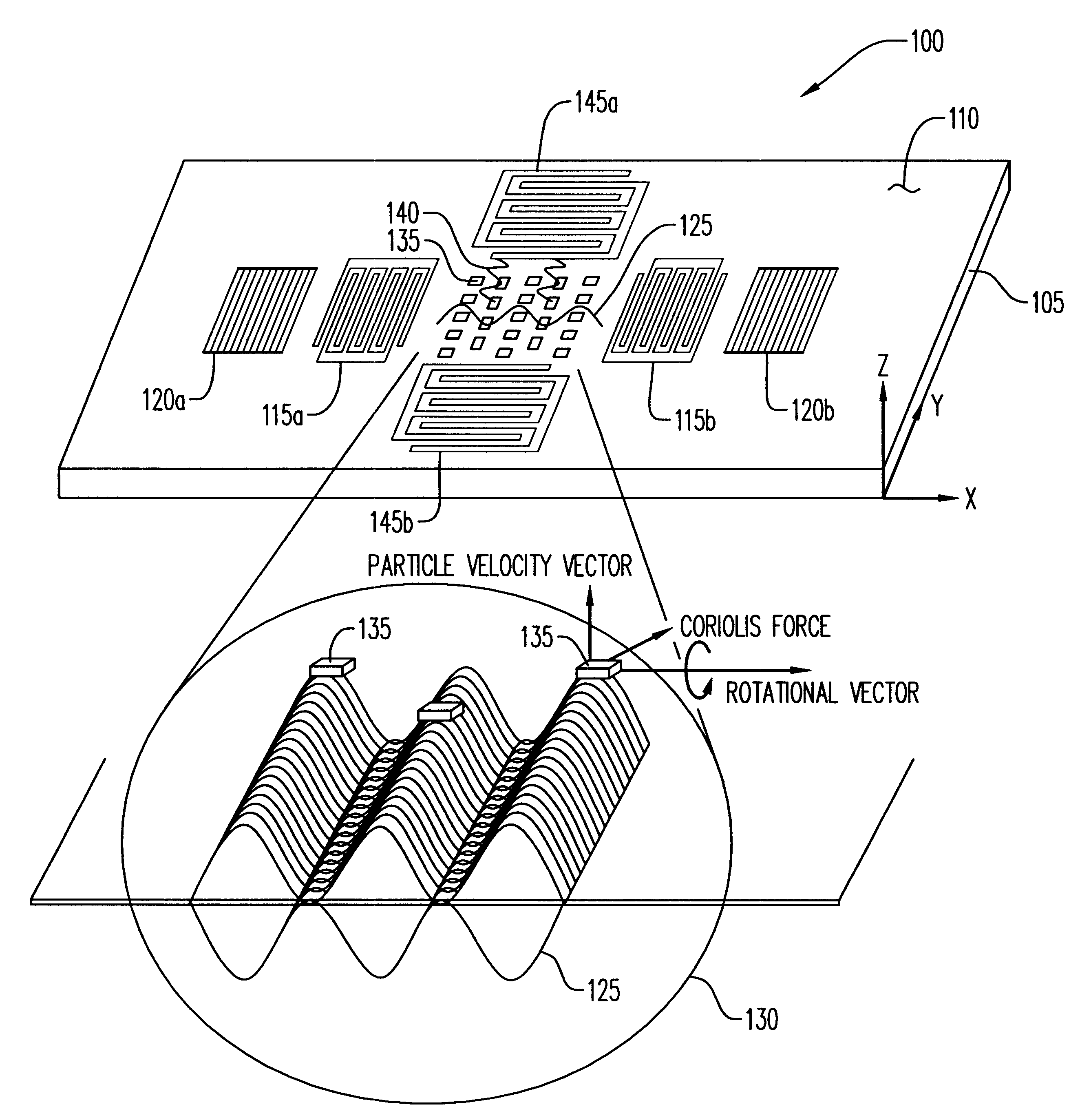
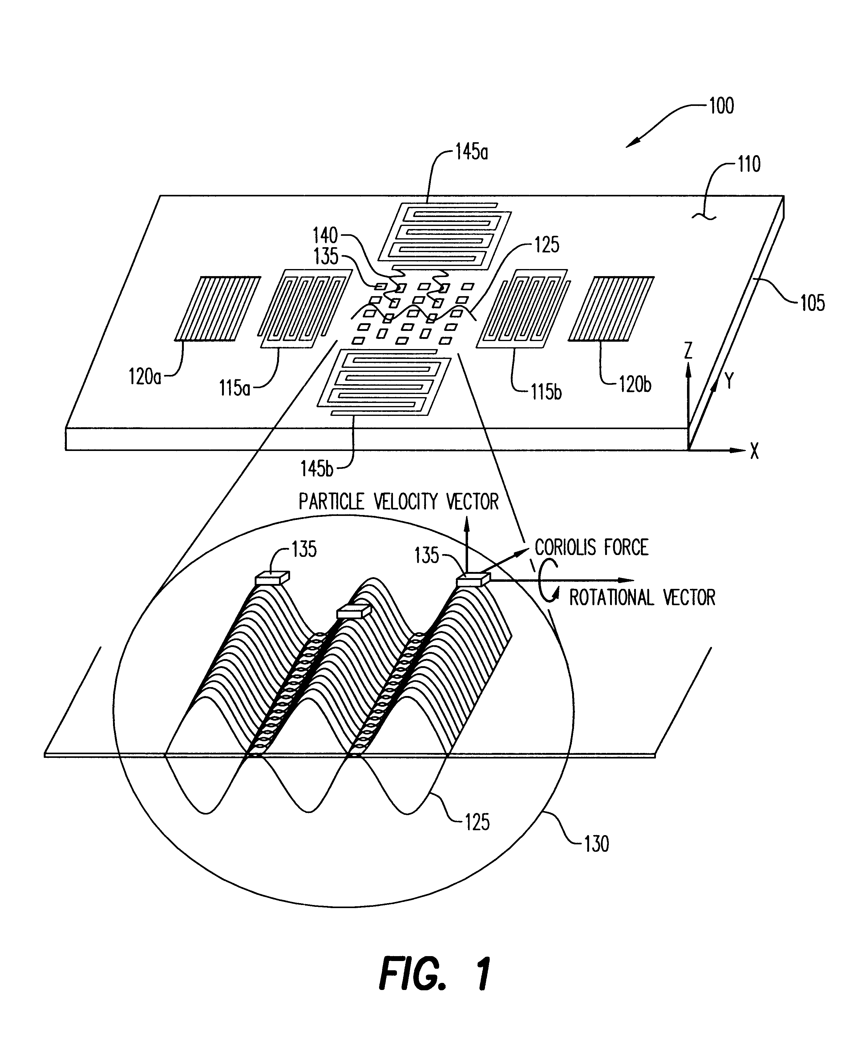
The present invention relates to a micro-electro-mechanical (MEM) gyroscope utilizing a surface acoustic wave (SAW) on a piezoelectric substrate, and more particularly to a combination of surface acoustic wave resonator (SAWR) and surface acoustic wave sensor (SAWS) technologies.

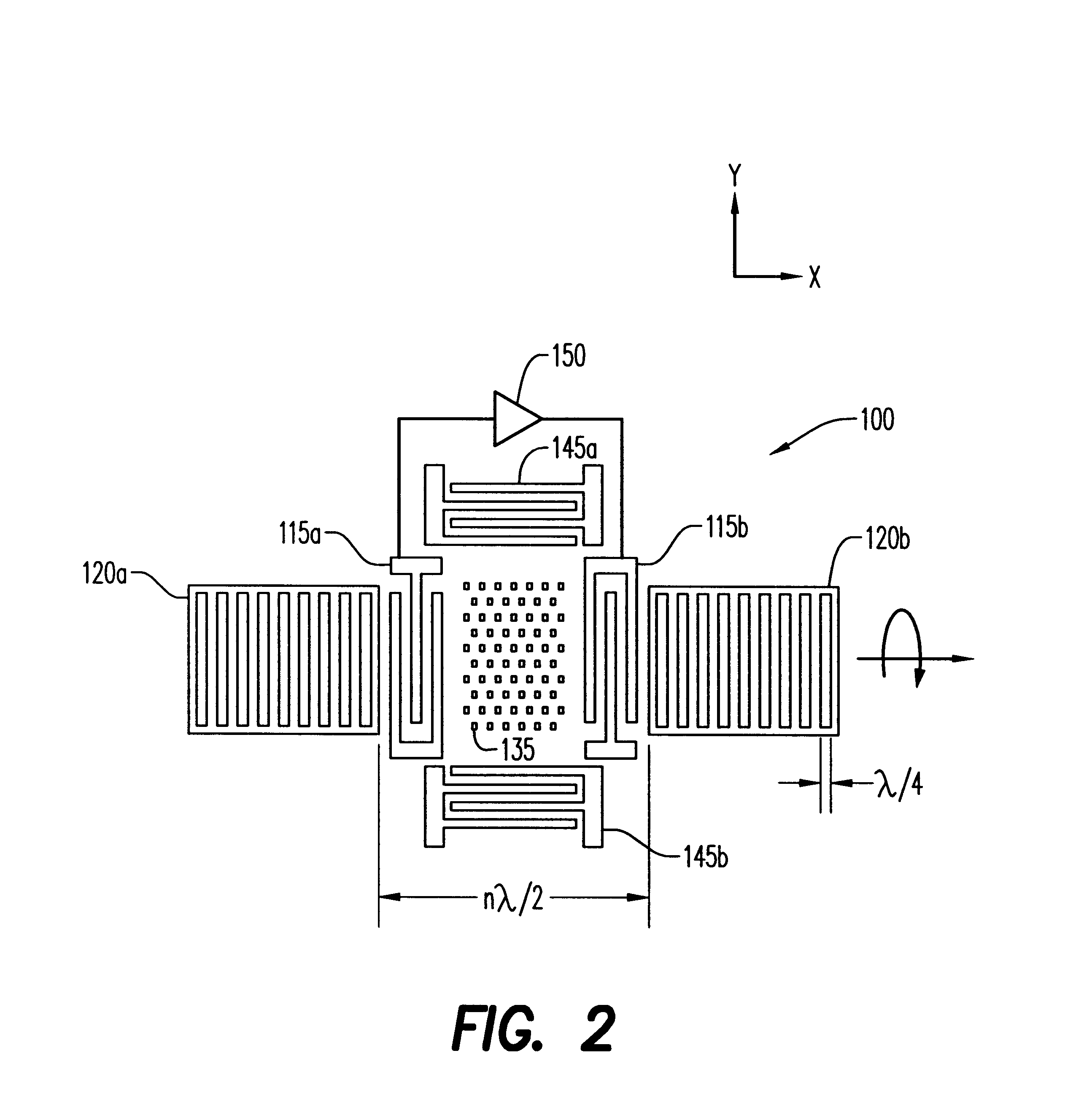
In accordance with the present invention, a first inter-digital transducer (IDT) functIoning as a resonator creates a SAW on a surface of a piezoelectric substrate. The SAW Propagates back and forth between a pair of reflectors and forms a standing wave within a region of the surface between the reflectors. A number of structures, e.g., metallic dots, are located within the region at anti-nodes of the standing wave. The structures experience a vibration perpendicular to the plane of the substrate, and the vibrating structures provide a reference vibrating motion for the gyroscope. When the substrate is rotated, the vibrating structures are subjected to a Coriolis force that generates a second surface acousti...


PUM


Abstract

A gyroscope comprises a piezoelectric substrate having a surface. Disposed on the surface are a resonator transducer, a pair of reflectors, a structure such as a metallic dot, and a sensor transducer. The resonator transducer creates a first surface acoustic wave on the surface. The pair of reflectors reflects the first surface acoustic wave to form a standing wave within a region of the surface between the pair of reflectors. The structure is disposed on the surface within the region, wherein a Coriolis force acting upon the structure creates a second surface acoustic wave. The sensor senses the second surface acoustic wave and provides an output indicative thereof.

Description

1. Field of the InventionThe present invention relates to gyroscopes, and more particularly, to a micro-electro-mechanical (MEM) gyroscope fabricated on a piezoelectric substrate.2. Description of the Prior ArtAn emergence of new consumer and automotive products that require angular velocity information has created an increasing demand for a smaller and inexpensive gyroscope or angular rate sensor. Rotating wheel gyroscopes, fiber optic gyroscopes and ring laser gyroscopes have been used extensively for inertial navigation and guidance systems; however, these gyroscopes are too bulky and expensive for newly emerging applications. A smaller and less expensive gyroscope is required for applications such as (i) automotive safety products, e.g., anti-skid system, ABS, airbag system, (ii) consumer products, e.g., 3-D pointer, camcorder, global positioning systems, sports equipment, (iii) industrial products, e.g., robots, machine control, guided vehicles, (iv) medical products, e.g., whe...

Claims


Application Information

Patent Timeline
IPC IPC(8): G01C19/56H03H9/02G01C19/5698H03H3/08H03H9/64
CPCG01C19/5698H03H9/6486H03H9/02645
Inventor VARADAN, VIJAY K.XAVIER, PASCAL B.SUH, WILLIAM D.KOLLAKOMPIL, JOSE A.VARADAN, VASUNDARA V.
Owner PENN STATE RES FOUND
Why Eureka
Try Eureka