Visual display

a technology for visual displays and displays, applied in the field of visual displays, can solve problems such as inconvenience in use, and achieve the effects of avoiding restarting, reducing overall weakness, and facilitating installation

Inactive Publication Date: 2003-02-11
COMPLETE MULTILAYER SOLUTIONS +1
View PDF14 Cites 23 Cited by
  • Summary
  • Abstract
  • Description
  • Claims
  • Application Information

AI Technical Summary

Problems solved by technology

This depth can render them inconvenient in use.

Method used


Image

  • Visual display
  • Visual display
  • Visual display

Examples


first embodiment

Description of Assembly Apparatus of the Invention

Referring to FIGS. 24 to 26, the assembly apparatus there diagrammatically shown has an assembly station 201 with a number of ancillary stations associated with it, in particular an emission device cleaning station 202, a sub-assembly pre-heating station 203, a face plate cleaning station 204, a face plate pre-heating station 205 and an evacuation unit 206. Components are moved between the stations by means whose design is within the ability of the man skilled in the art and will not be described here.

The emission device cleaning station 202 incorporates a cleaning emission device 101, as described below, set up for cleaning emission devices 1 to be assembled. The sub-assembly pre-heating station 203 incorporates heaters (not shown) for heating a sub-assembly of however many--four as shown in FIG. 26--of the emission devices 1 on their carrier 40 as will be assembled into a visual display. The face plate cleaning station 204 has anot...

second embodiment

Description of Combined Assembly and Sealing Apparatus

Turning now to FIGS. 32 to 35, the apparatus there shown is for assembling face plates 753 to pre-assembled emission devices and carriers 754, referred to below as cathodes.

The emission devices and carriers are pre-assembled in a station--not shown--which heats them to melt the solder joining them and cools them to set the solder.

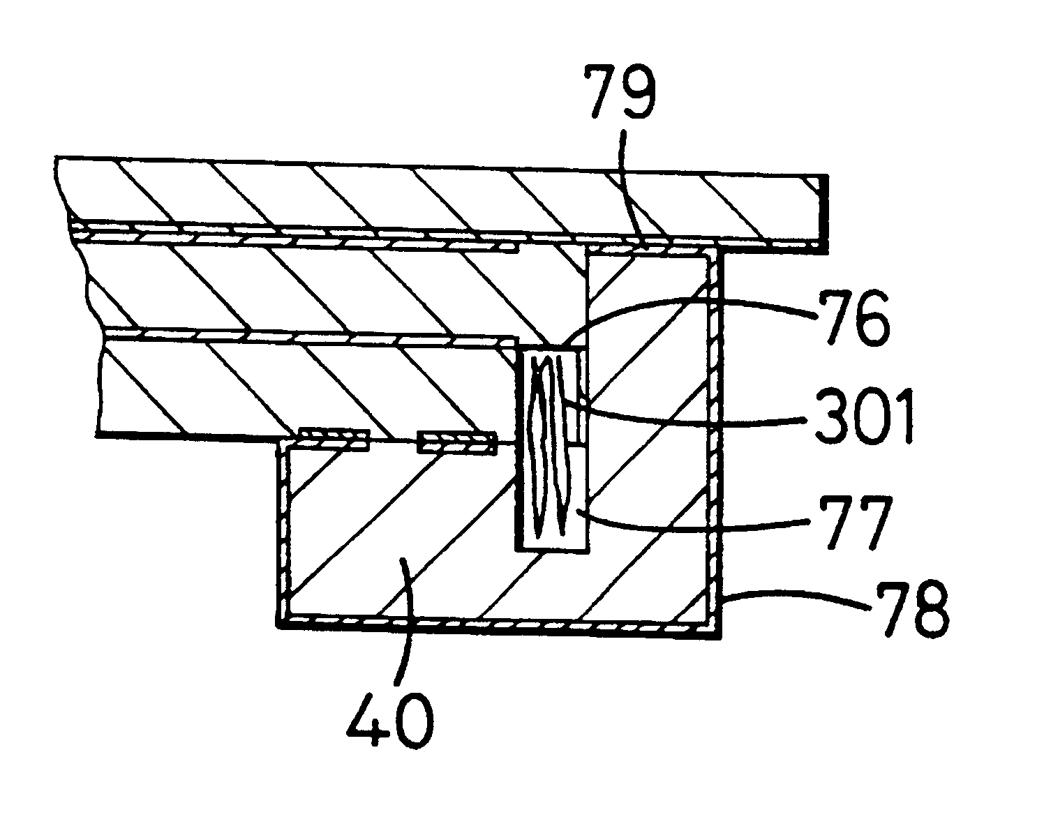
Use of emission devices cut to fit their carrier avoids the need for manipulating them with respect to the carrier. Getter strips 301 are added to the channels 77, to complete pre-assembly of the cathodes.

The apparatus has three stations 701,702,703. The first 701 is a preheater, the second 702 is an alignment and irradiation station and the third 703 is a controlled cooling station. A conveyor 704 is provided for feeding superimposed face plates and cathodes through a first gate valve 705 into the preheater. Thence, an internal conveyor operable by a knob 706 moves them through another gate valve 707 to...


PUM


Abstract

The apparatus for sealing face plates (753) and cathodes (754) has three stations (701, 702, 703). The first (701) is a preheater, the second (702) is an alignment and irradiation station and the third (703) is a controlled cooling station. Beneath each station, a vacuum pump (710) capable of drawing ultralow pressures is provided. The preheater is equipped with upper and lower banks of radiant heaters and reflectors (712). The upper heaters are Provided above a quartz: window (713) of a chamber (714) constituting the station. The pressure in the preheater is pumped down to that in the alignment and irradiation station prior to opening of the gate valve between them and transfer of the face plate and cathode. At the alignment and irradiation station, further heaters (716) are provided. Those above the face plate and cathode, the face plate being uppermost, are mounted on frames (717) about hinges (718), whereby they can be swung up to clear this station's top quartz window, exposing the face plate to the view of an optical system (719) and a laser (720). Manipulation controls (722) are provided for manipulating the position of the face plate to be pixel alignment, as measured by the optical system (719), with the cathode. The laser is traversed around further. The cooling station (703) has meanwhile been pumped down and the sealed device is transferred to it. The temperature of the device is allowed to rise very slowly, in order to reduce the risk of thermal cracking to as great an extent as possible. As the temperature slowly falls, air is slowly introduced, so that the finished device can be removed to the ambient surroundings.

Description

The present invention relates to a visual display, particularly though not exclusively for use with data processing apparatus.Visual displays for data processing apparatus, such as computers, are normally field emission displays of the cathode ray tube type. These generally have a depth of the order of their size dimension, which conventionally is their corner to corner or diagonal dimension. This depth can render them inconvenient in use. Recently, laptop computers have become increasingly widely used. These incorporate a "flat" screen display, usually of the liquid crystal type.Proposals have been made to provide displays having flat screen cathode ray tubes. These are known as Spindt cathodes, after the inventor of U.S. Pat. No. 3,755,704. In this specification, they are referred to as field emission devices.OBJECT OF THE INVENTIONThe object of the present invention is to provide an improved method of sealing a "flat" screen field emission visual display and a machine therefor.Th...

Claims


Application Information

Patent Timeline
Patent Type & Authority Patents(United States)
IPC IPC(8): H01J29/94H01J29/00H01J31/12H01J9/00H01J9/46H01J9/26H01J9/24H01J9/32H01J9/36H01J9/38H01J9/385H01J9/39H01J29/46H01J29/86H01J29/87H01J29/90H01J29/92
CPCH01J9/261H01J9/46H01J29/92H01J29/94H01J31/127H01J2329/92H01J2209/261H01J2329/867H01J2329/90
Inventor COOPER, ANTHONY JOHNPOTHOVEN, FLOYD R
Owner COMPLETE MULTILAYER SOLUTIONS
Why Eureka
Try Eureka