Method for forming fiber reinforced composite parts

a fiber reinforced composite and composite part technology, applied in the direction of friction lining, transportation and packaging, other domestic articles, etc., can solve the problems of long manufacturing process, slow process, time-consuming process,

Inactive Publication Date: 2003-02-18
HONEYWELL INT INC
View PDF15 Cites 61 Cited by
  • Summary
  • Abstract
  • Description
  • Claims
  • Application Information

AI Technical Summary

Problems solved by technology

However, past manufacturing processes for producing these fiber-reinforced composite structures were often lengthy undertakings, requiring months to fabricate a single part.
In one example, a typical fiber-reinforced composite part was prepared by a non-woven process that involved needle-punching layers of carbon fibers to form a preform, a slow, time-consuming process.
For this reason, it often took a term of several months to obtain a final product, causing the product to be extremely expensive.
Further, much material was wasted in order to obtain the final product.
Again, this process requires extensive time and wastes material in order to obtain the final product.
Thus, longer chopped fibers (1-11 / 2 inches (about 2.5-3.8 cm)) do not work well in this liquid slurry method, since a uniform dispersion of fibrous material and resin powder in the slurry cannot be attained with the longer chopped fiber lengths.
The longer fibers tended to "ball-up" during mixing with the powdered resin and during deposition into the mold, making it difficult to obtain a uniform end product.
Moreover, this "balling effect" directly contributed to the "loftiness" of the preform, a disadvantageous result of the water slurry method since a lofty preform was difficult to control within the mold.
Further, apparatus 100 of FIG. 1 is limited to a single-batch process, i.e., to make one final fiber-reinforced composite part, the individual proportions for each fibrous material and binder material have to be weighed and added individually for each preform made.
However, such a process requires the use of excess carbon matrix material, a curing step under pressure after formation of an intermediate-formed part such as a preform or mold, and also requires subsequent carbonization and graphitization of the cured intermediate part, both under pressure, to obtain the final fully-densified composite part.
However, it is costly and time consuming to perform the curing, carbonization and graphitization all under pressure.

Method used


Image

  • Method for forming fiber reinforced composite parts
  • Method for forming fiber reinforced composite parts
  • Method for forming fiber reinforced composite parts

Examples


Embodiment Construction

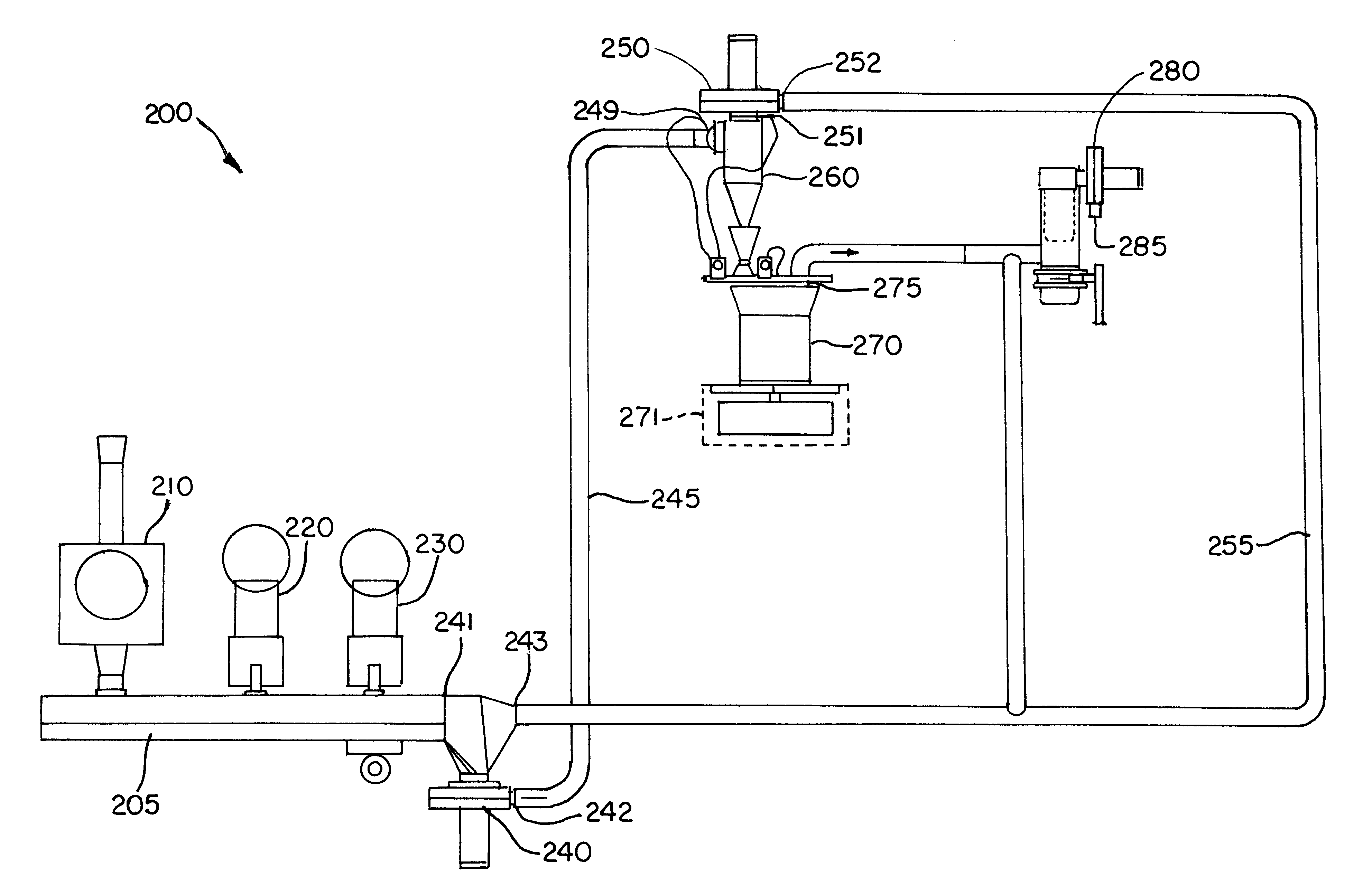
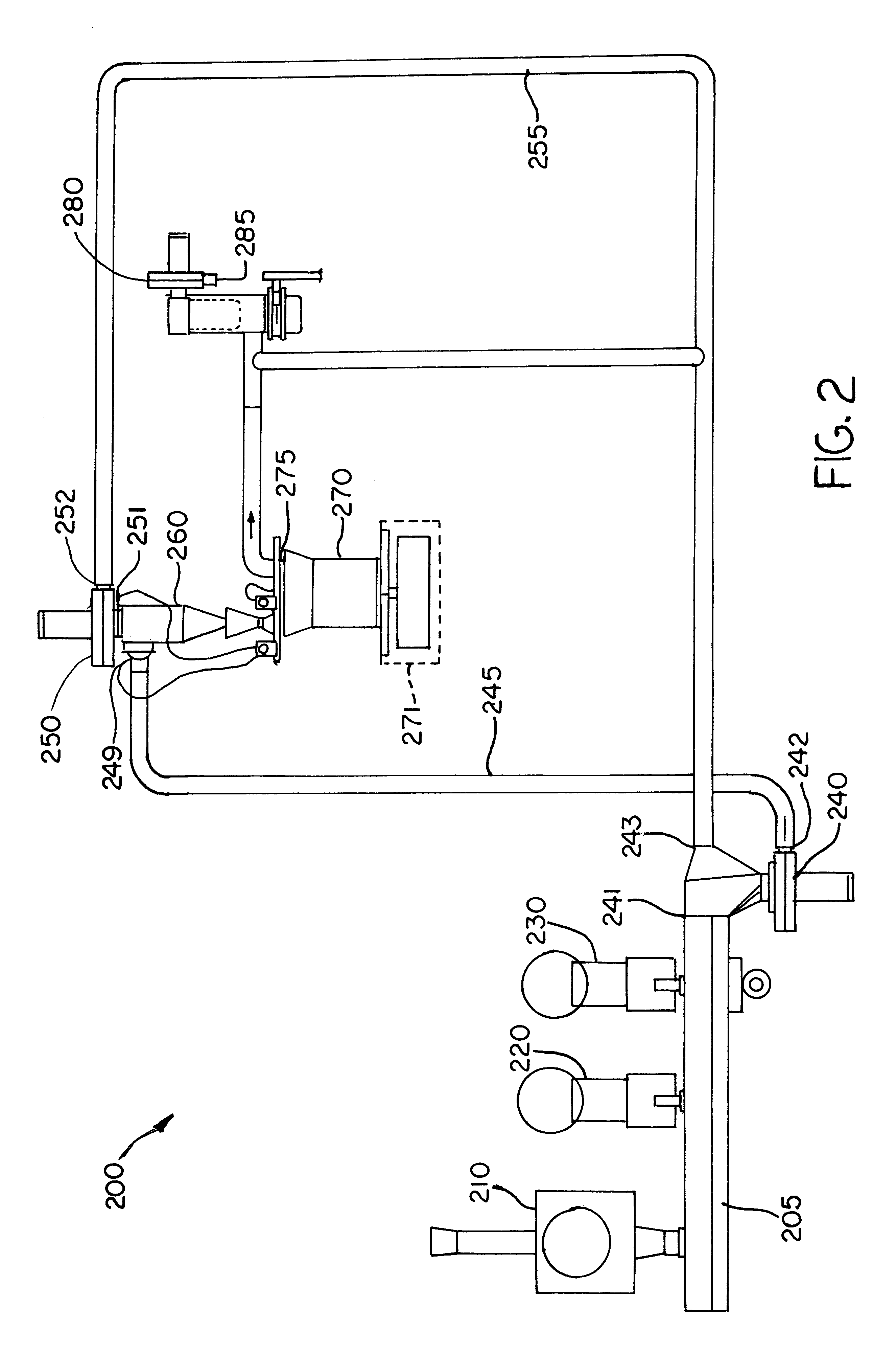
Several test parts were fabricated using the above method and apparatus, specifically nine (9) stator and six (6) rotor-size parts for 767 aircraft made by the BOEING Corporation. For a stator, 3.976 pounds (1807 g) of 1-inch (2.54 cm) chop length carbon fiber (grade X9755) and 1.454 pounds (661 g) of milled carbon fiber (grade 341, each grade of fibers marketed by FORTAFIL), and 7.176 pounds (3262 g) of AR mesophase pitch resin (pellets ground into powder) marketed by the MITSUBISHI Gas Chemical Corporation were dispensed onto a belt conveyer over approximately a thirteen (13) minute period (a total of 12.606 pounds or 5723 g of "mixed material" was deposited in the mold over the time period to form a preform). The material handling fan was operating at 80% of the maximum motor speed, the return air fan at 37% of maximum motor speed and dust collector fan at 60% of maximum motor speed. The mold was located at a 2.5 inch (6.35 cm) linear position from the centerline of the cyclone d...


PUM

PropertyMeasurementUnit
lengthaaaaaaaaaa
densitiesaaaaaaaaaa
lengthaaaaaaaaaa

Abstract

A method and apparatus for combining raw fibrous and binding materials in a single mixing step (Step S3), followed by consolidation (Step S5) so as to greatly shorten the overall cycle time to a finished fiber-reinforced composite part. Chopped fibrous materials and binder materials are deposited sequentially onto a belt conveyor (Step S2) so that the materials are successively layered, one on top of each other in a predetermined ratio, and subsequently mixed (Step S3) to achieve uniform dispersion throughout. The mixed materials are then deposited into a rotating mold (Step S4) to further ensure uniform dispersion of fibrous and binder materials. Impregnation of the fibrous materials with the binder material occur in-situ as the uniformly mixed materials are heated and subsequently compacted in the mold (Step S5) to obtain the desired shape of the fiber-reinforced composite part.

Description

1. Field of the InventionThe present invention relates to a method and apparatus for forming fiber reinforced composite parts.2. Description of the Related ArtFiber-reinforced composite structures, such as carbon-carbon composites for example, are widely used as friction materials for heavy-duty brakes in automobiles, trucks, and aircraft. This is because they exhibit high thermal conductivity, large heat capacity, and excellent friction and wear characteristics and thus can provide excellent performance.However, past manufacturing processes for producing these fiber-reinforced composite structures were often lengthy undertakings, requiring months to fabricate a single part. In one example, a typical fiber-reinforced composite part was prepared by a non-woven process that involved needle-punching layers of carbon fibers to form a preform, a slow, time-consuming process. When two or more layers of fibers are needle punched together by metal needles having barbs on one end, the barbs ...

Claims


Application Information

Patent Timeline
Patent Type & Authority Patents(United States)
IPC IPC(8): B29B15/10B29B15/12C04B35/83F16D69/02
CPCC04B35/83F16D69/023C04B2235/526C04B2235/5272Y10T428/30Y10S425/108B29B15/105B29B11/16
Inventor WOOD, MICHAEL D.LAFOREST, MARK L.MURDIE, NEILKRISKOVICH, DEAN S.HUDALLA, VERNON R.GONSOWSKI, THADDEUS W.
Owner HONEYWELL INT INC
Why Eureka
Try Eureka