Knitted two-dimensional heating element

a heating element and two-dimensional technology, applied in the field of two-dimensional heating elements, can solve the problems of increasing and undesirable heat at the connection, consuming a large amount of heating conductor material during the connection, and high heat loss in the area of contact conductors

Inactive Publication Date: 2003-03-11
I G BAUERHIN GMBH
View PDF8 Cites 20 Cited by
  • Summary
  • Abstract
  • Description
  • Claims
  • Application Information

AI Technical Summary

Benefits of technology

The apparatus according to the present invention for producing two-dimensional textile heating elements includes needles for knitting heating conductors onto a textile base material, at least one guide rail for guiding the needles, and at least one sensor system arranged for detecting contact conductors and / or markings applied to the textile base material to control the at least one guide rail. This apparatus ensures the reproducibility of the heating-conductor pattern already mentioned above and allows relatively free control of the guide rails to produce the two-dimensional heating elements according to the present invention.
In the method according to the present invention for producing a two-dimensional heating element that includes contact conductors and heating conductors which are electrically conductive and contact one another to produce an electrical connection therebetween, the contact conductors are applied to a textile base material before the knitting process such as, for example, by adhesive bonding or sewing. In a subsequent knitting process, the heating conductors are connected to the textile base material and the contact conductors. During the knitting process, a sensor system of the apparatus for producing the two-dimensional heating element fitted upstream of needles of a knitting machine detects the contact conductors and / or markings applied to the textile base material and produces sensor signals in response to the detection of the contact conductors and / or markings. The markings may, for example, include stamped-out portions or metal pieces. The at least one guide rail of the knitting machine is controlled in response to the sensor signal. This method necessitates reproducible and simultaneously relatively free and cost-effective control. The control is carried out by the at least one guide rail of the knitting machine which is moved in response to data supplied by the sensor system and according to internally stored data via an electrical or hydraulic drive controlled by a computer. Ultimately, appropriate modification of the program of the computer may be made for changing the pattern of the heating areas. Accordingly, different heating capacities may be implemented.
The heating areas are the areas in which the heating conductors are knitted onto the base material to form a required pattern. The course of the heating conductors in the area of the contact conductors along the stitch wales leads to a more permanent connection of these conductors to the contact conductors, thereby reducing the undesired inherent heating of the individual contact strips. Outside the heating areas and / or inside the contact conductors, heating conductor material is also saved by this guiding technique of the heating conductors along the stitch wales.
In a further embodiment, the heating conductors float and are not woven in to the textile base material outside the heating areas and the contact conductors. Accordingly, when the textile base material is cut to size, the heating conductors sticking out at the respective ends may be shortened more easily. This facilitates the prevention of inadvertent contacts of the heating conductors with the surrounding materials and therefore reduces the possibility of potential short circuits.
Furthermore, the contact conductors are metallic conductors such as, for example, copper conductors which may generally be produced cost-effectively.

Problems solved by technology

If there is a deficient connection between the heating conductors and the contact conductors, a high contact resistance results which produces an increased and undesirable development of heat at the connection (the heat is certainly not intended to accumulate at these contact points but is intended to be distributed over the individual heating conductors).
The heat loss in the area of the contact conductors is often too high to provide adequate heating in the desired area.
Furthermore, a great deal of heating conductor material is often consumed during the manufacturing process in the spaces between the individual heating elements being manufactured.

Method used


Image

  • Knitted two-dimensional heating element
  • Knitted two-dimensional heating element
  • Knitted two-dimensional heating element

Examples


Embodiment Construction

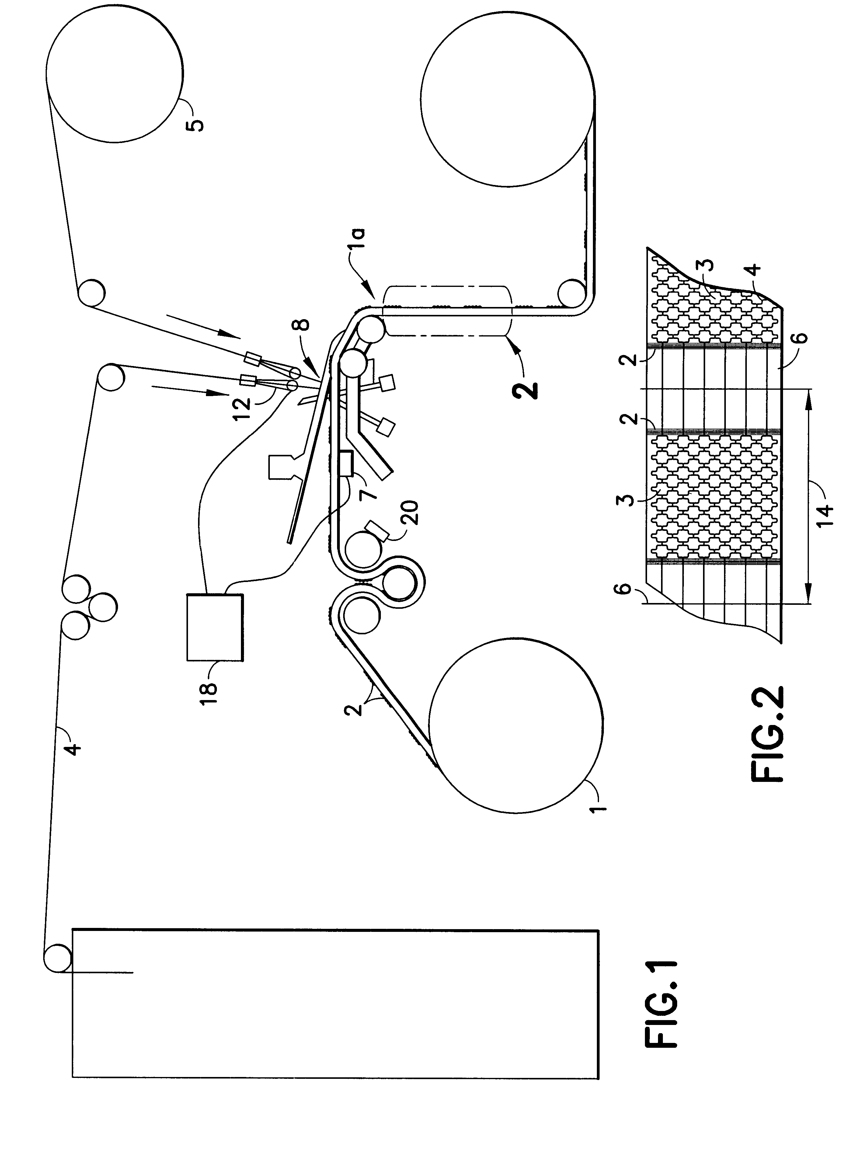
FIG. 1 is a schematic diagram showing an apparatus for producing a two-dimensional heating element according to a method of the present invention.

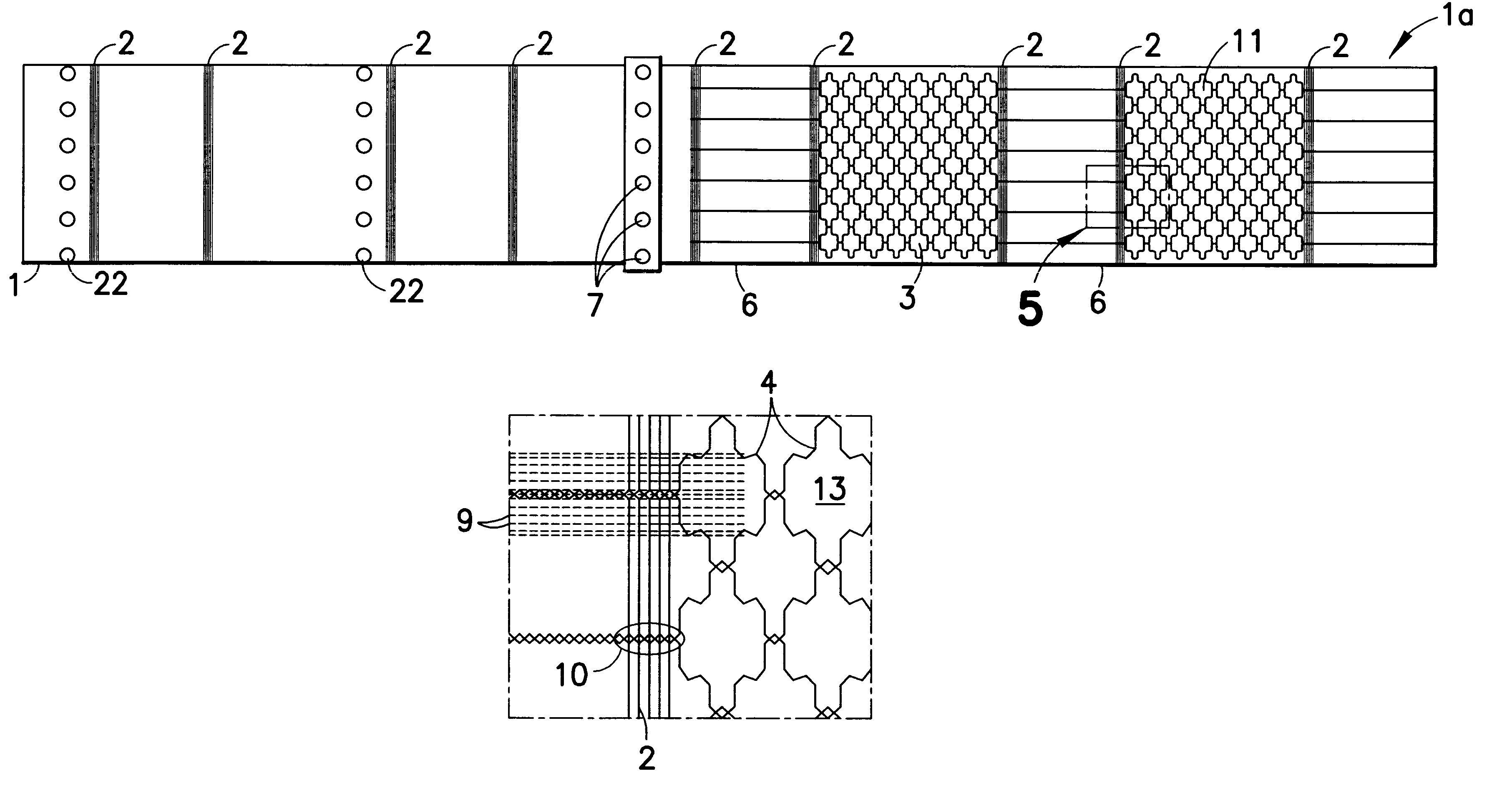
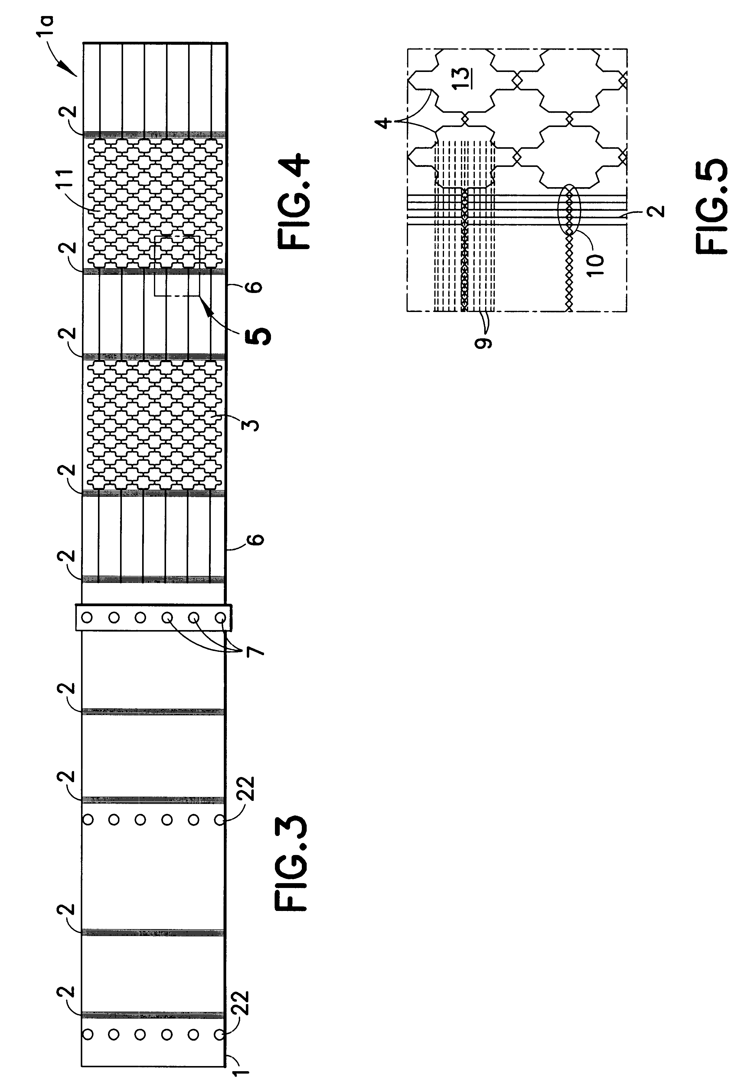
According to this method, a base material 1 such as, for example, a textile fabric, a knitted fabric, or a nonwoven fabric having contact conductors 2 is led from a roll and over a number of guide rollers, past a sensor system 7, to a knitting machine including a guide rail 12 and needles 8 required for the knitting process.

At the same time, heating conductors 4 (only one heating conductor 4 is shown in FIG. 1) are led over a number of guide rollers and fed to the guide rail 12. The guide rail 12 is controlled via the sensor system 7 by a computer 18. The sensor system 7 detects and processes the positions of the individual contact conductors 2. Accordingly, defined control of the guide rail 12 may be effected in response to the positions of the contact conductors 2.

To fix the heating conductor onto the base material 1, a textile thread 5 ...


PUM

PropertyMeasurementUnit
electrically conductiveaaaaaaaaaa
heating capacityaaaaaaaaaa
areaaaaaaaaaaa

Abstract

A two-dimensional heating element, especially for seat heaters in the motor vehicle sector, having a textile base material and contact conductors and heating conductors which are electrically conductive and touch one another. The contact conductors delimit heating areas. The heating conductors are laid effectively in the direction of stitch wales and orthogonal to the stitch wales in such a way that there are at least two zones functioning at least as a main heating area and at least as a secondary heating area with different heating capacities.

Description

1. Field of the InventionThe present invention relates to a two-dimensional heating element for a seat heater in a motor vehicle having a textile base material and contact conductors and heating conductors which are electrically conductive and touch one another. The present invention further relates to a method of producing the two-dimensional heating element having contact conductors and heating conductors which are electrically conductive and touch one another. Furthermore, the present invention relates to an apparatus for producing the two-dimensional textile heating element according to the invention via a knitting process.2. Description of the Related ArtFor many years, electrical two-dimensional heating elements have been known which have a textile base material and electrically conductive contact and heating conductors. In general, two contact strips are arranged opposite one another and the heating conductors run from one contact strip to the other (see EP 0 541 047 A3, EP 0...

Claims


Application Information

Patent Timeline
Patent Type & Authority Patents(United States)
IPC IPC(8): H05B3/34D04B21/16D04B27/24D04B27/34
CPCD04B21/16D04B27/24D04B27/34H05B3/34H05B2203/002Y10T29/49083H05B2203/014H05B2203/017H05B2203/029H05B2203/037H05B2203/011
Inventor MICHELMANN, JOCHEN
Owner I G BAUERHIN GMBH
Why Eureka
Try Eureka