Heat treatment method and heat treatment apparatus

a heat treatment method and heat treatment technology, applied in lighting and heating equipment, household stoves or ranges, coatings, etc., can solve the problems of low-k film oxidation and degradation, worrisome possibility, and difficult to make a complete vacuum or non-reactive gas atmosphere, so as to prevent the oxidation of an interlayer insulating film and excellent reducibility.

Inactive Publication Date: 2009-12-31
TOKYO ELECTRON LTD
View PDF8 Cites 6 Cited by
  • Summary
  • Abstract
  • Description
  • Claims
  • Application Information

AI Technical Summary

Benefits of technology

[0006]It is an object of the present invention to provide a heat treatment method and a heat treatment apparatus capable of surely preventing oxidation of an interlayer insulating film of a low dielectric constant and / or a metal film.
[0014]In accordance with the present invention, a substrate having an interlayer insulating film of a low dielectric constant and / or a metal film is accommodated in a processing chamber. An organic compound including at least one of carboxylic acid anhydride, ester, organic acid ammonium salt, organic acid amine salt, organic acid amide, organic acid hydrazide, organic acid metal complex, and organic acid metal salt having excellent reducibility without polymerization which occasionally occurs in aldehyde or carboxylic acid is supplied into the processing chamber while controlling its flow rate. Then, the substrate is heated in an atmosphere of the organic compound. Accordingly, it is possible to surely prevent oxidation of an interlayer insulating film of a low dielectric constant and / or a metal film by a reduction reaction of the organic compound. Further, it is possible to prevent occurrence of an error in an actual flow rate and a flow rate set by controlling a flow rate of the organic compound supplied into the processing chamber, thereby sufficiently ensuring process reproducibility.

Problems solved by technology

However, it is very difficult to make a complete vacuum or nonreactive gas atmosphere, and impurities such as oxygen can be easily contained in the atmosphere.
Accordingly, in these methods, there is a worrisome possibility that the low-k film may be oxidized and degraded due to oxygen contained in the atmosphere.
However, since Cu is easily oxidized to form oxide on the Cu line, in the heat treatment, there is a worrisome possibility that a metal film is oxidized due to oxygen contained in the atmosphere.

Method used


Image

  • Heat treatment method and heat treatment apparatus
  • Heat treatment method and heat treatment apparatus
  • Heat treatment method and heat treatment apparatus

Examples


Embodiment Construction

[0021]Hereinafter, embodiments of the present invention will be described in detail with reference to the accompanying drawings which form a part hereof.

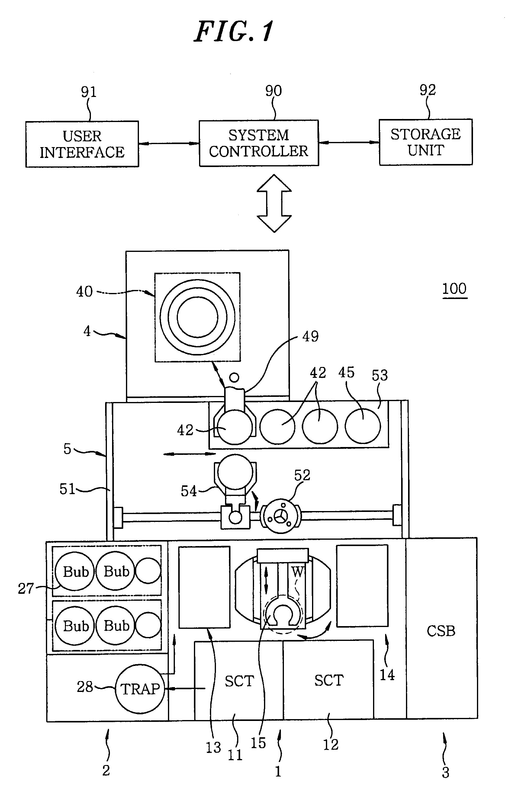
[0022]FIG. 1 schematically shows a plan view of a wafer processing system including a heat treatment apparatus capable of performing a heat treatment method in accordance with the present invention.

[0023]The wafer processing system 100 includes a process station 1 having multiple units for performing a specific process on a wafer W serving as a semiconductor substrate, a side cabinet 2 and a carrier station (CSB) 3 provided at opposite sides (left and right sides in FIG. 1) of the process station 1, a heat treatment unit 4 provided at a rear side (upper side in FIG. 1) of the process station 1 to perform a heat treatment on the wafer W, and an interface station 5 provided between the process station 1 and the heat treatment unit 4 to perform a delivery of the wafer W therebetween.

[0024]The process station 1 includes coating process ...


PUM

PropertyMeasurementUnit
temperatureaaaaaaaaaa
dielectric constantaaaaaaaaaa
flow rateaaaaaaaaaa

Abstract

Disclosed is a heat treatment method including a step of placing a wafer W provided with a low-k film and a metal layer in a heat treatment furnace 41, a step of supplying gaseous acetic anhydride into the heat treatment furnace 41, while controlling the flow rate using a mass flow controller 44d, and a step of heating the wafer W in the heat treatment furnace 41 supplied with gaseous acetic anhydride by using a heater 41b provided in the heat treatment furnace 41.

Description

FIELD OF THE INVENTION[0001]The present invention relates to a heat treatment method and a heat treatment apparatus for performing a heat treatment on a substrate such as a semiconductor substrate having an interlayer insulating film of a low dielectric constant (low-k film) and / or a metal film of, e.g., copper (Cu).BACKGROUND OF THE INVENTION[0002]Recently, it is required to reduce capacitance between lines and improve conductivity of lines and electromigration tolerance to meet demands for a high speed semiconductor device, miniaturization of an interconnection pattern and high integration. A Cu multilayer interconnection technique, in which copper (Cu) having high conductivity and excellent electromigration tolerance is used as an interconnection material and a low dielectric constant (low-k) material is used in an interlayer insulating film, has been given attention as a technique in response to the requirements.[0003]The interlayer insulating film made of a low dielectric const...

Claims


Application Information

Patent Timeline
Patent Type & Authority Applications(United States)
IPC IPC(8): H01L21/26F24C1/00
CPCC23C16/56H01L21/02068H01L21/3105H01L21/76883H01L21/67109H01L21/76826H01L21/76828H01L21/31058
Inventor MIYOSHI, HIDENORINARUSHIMA, MASAKI
Owner TOKYO ELECTRON LTD
Why Eureka
Try Eureka