It is another object of the invention to provide an earth boring bit that does not spill the earth from the bored hole onto the ground around and near the hole as the hole is being bored.
According to yet another preferred embodiment of the invention, the teeth on each of the exterior
cutting members form a cutting edge extending beyond said outer edge of the plate and having an
effective diameter extending beyond the
diameter of the plate for reducing friction on the exterior of the drum as the earth boring bit rotates.
Each row of cutting teeth 47A,47B,47C and 47D is preferably attached to the corresponding cutting plate 46A, 46B, 46C or 46D at least a 35 degree angle ".theta." from a bottom surface 36 of the plate 30. As shown in FIG. 4, the inner cutting members 42A and 42B are positioned adjacent the
pilot bit 41 and opposite one another so that the respective rows of teeth 47A and 47B extend outwardly away from and are positioned perpendicular to the plate shaft extension 31 A and bit 41. The outer cutting members 43A and 43B are positioned adjacent an outer edge 37 of the plate 30 and opposite one another so that the respective rows of teeth 47C and 47D likewise extend outwardly away from and are positioned perpendicular to the plate shaft extension 31 A and bit 41. Furthermore, each outer cutting member 43A and 43B is positioned on the plate 30 so that outer end 49A and 49B of the respective cutting members 43A and 43B each extend beyond the outer edge 37 of the plate 30. Positioning the outer cutting members 43A and 43B on the plate 30 in this manner causes the outer cutting members 43A and 43B to
cut slices of earth which form a hole having a
diameter which is slightly larger than diameter of the exterior sidewalls 24 of the drum 20. This reduces friction on the exterior sidewalls 24 during operation, thus extending the life of the drum 20 and earth boring bit 10. When in use, the inner and outer cutting members 42A, 42B and 43A, 43B collectively
cut circular slices of earth having a diameter slightly greater than the diameter of the plate 30.
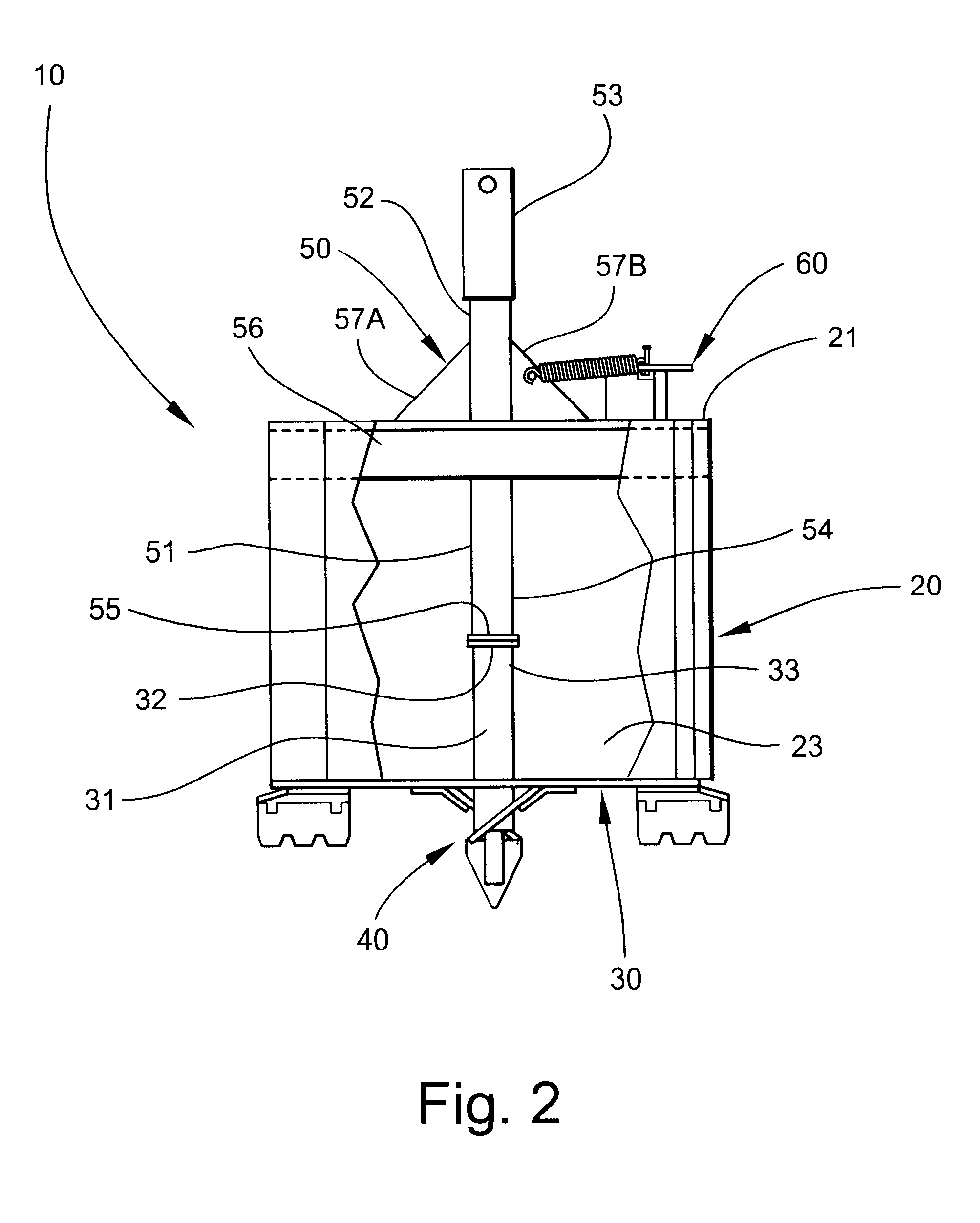
Referring now to FIG. 5, the earth boring bit 10 is shown with the outer cutting member 43B removed to show the
handle assembly 60. The
handle assembly. 60 includes an elongate rod 61 having first and second ends 62 and 63. The rod 61 preferably has a diameter of 3 / 4 inch and is positioned within and extends through the interior of the drum 20 adjacent the interior sidewall 23. The rod 61 is received and held by a tube support 66 which is attache to the interior sidewall 23 of the drum 20. The tube support provides enhanced stability and support to the rod 61. A latch
handle 64 is attached to the first end 62 of the rod 61, and is interconnected to the support
flange 57B by a spring 65. Complementary
zinc nuts and bolts 65A and 65B connect the spring 65 to the
flange 57B and the handle 64. The spring 65 is preferably a compression spring, and cooperates with the latch handle 64 to move the handle
assembly 60 between, and maintain the handle assembly 60 in, the open and closed positions.
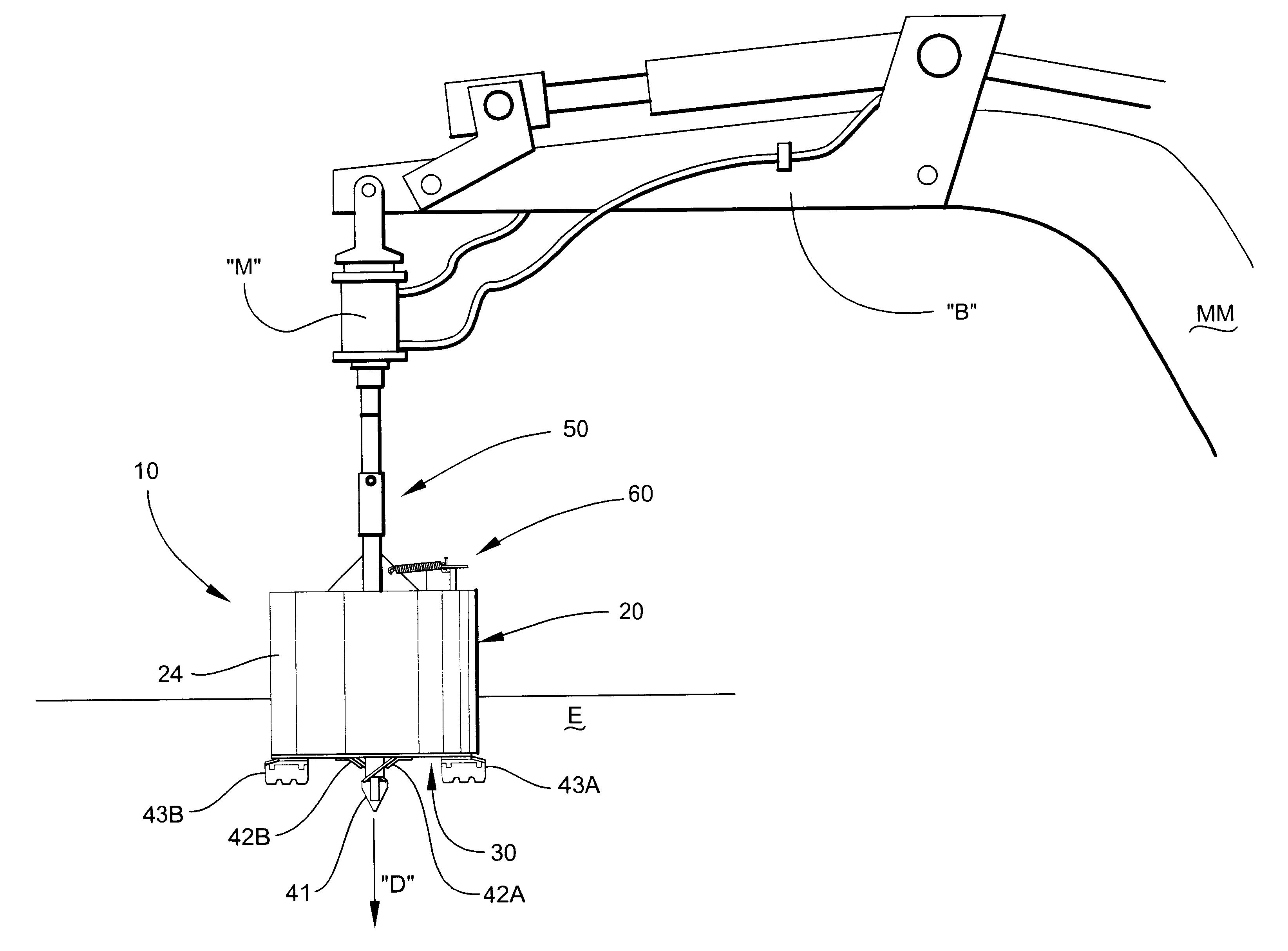
Referring now to FIGS. 6, 7 and 8, the earth boring bit 10 is shown being used to bore a hole into the earth. The earth boring bit iO is shown in FIGS. 6, 7 and 8 connected to a
hydraulic motor "M" which is connected to the boom "B" of a mobile
machine "MM". To use the earth boring bit 10 to bore a hole, the earth boring bit 10 is centered over the site where the hole is to bored and is lowered into position in the direction "D" shown. The
pilot bit 41 maintains the
machine 10 in position while the
hydraulic motor "M" is actuated, which in turn causes the drive assembly 50 to rotate the drum 20 and plate 30. The overall design of the earth boring bit and the angle of the teeth on the inner and outer cutting members 42A, 42B and 43A, 43B causes the earth boring bit 10 to begin cutting away a slice of the earth "E" as the earth boring bit 10 rotates. As the rows of teeth 47A, 47B, 47C and 47D on the cutting members 42A, 42B, 43A and 43B continue to
cut into the earth "E", the upturned earth "E" is pushed into the interior of the drum 20. The depth of the hole being bored can accurately be determined by observing that portion of the drum 20 which is still above the ground. The drum 20 may alternatively include markings on the exterior sidewall 24 for further facilitating the accuracy of the cut (not shown). Furthermore, the earth boring bit 10 can be withdrawn from the hole during the boring process to check the depth of the hole. Cuts up to 12 inches can be made in a single operation, based upon
soil type and density. As discussed above, the plate 30 cooperates with the drum 20 to prevent earth "E" from falling back into the hole as the earth boring bit 10 is removed therefrom.
