Chamber cleaning mechanism

a cleaning mechanism and chamber technology, applied in the direction of machines/engines, solid removal, pipe elements, etc., can solve the problems of high toxic effluent gas, corrosion and buildup, and the blade assembly of the currently available rccm often lacks the strength to cut through the deposits formed on the reaction chamber wall

Inactive Publication Date: 2003-04-08
APPLIED MATERIALS INC
View PDF18 Cites 15 Cited by
  • Summary
  • Abstract
  • Description
  • Claims
  • Application Information

AI Technical Summary

Benefits of technology

In one aspect of the present invention, the blades of the reactor chamber cleaning apparatus are double-edged. Moreover, the blades preferably have a width and the reciprocating member has a range of movement, which width and range of movement are selected to provide each blade with a rotational path which overlaps with the rotational path of another blade. The blades are preferably from about 0.65 to about 0.75 inches wide, more preferably about 0.70 inches wide, and the rotation range is about 90.degree..
In another aspect, the reciprocable member of the reactor chamber cleaning apparatus is a piston of an air cylinder. The air cylinder is preferably equipped with a mechanism for indicating whether the cylinder is sufficiently extending and / or retracting to ensure that the apparatus is properly cleaning the chamber. For example, the mechanism may comprise one or more appropriately positioned magnetic reed switches. The mechanism for indicating whether the cylinder is sufficiently extending and retracting is preferably configured to provide an output, such as an electronic signal, indicative of whether the cylinder is sufficiently extending and / or retracting. The electronic signal may be transmitted to a CPU for further processing and / or may trigger an alarm, such as an audible alarm to indicate that the cylinder is not sufficiently extending and / or retracting.

Problems solved by technology

Certain chemical vapor deposition processes, particularly those associated with large scale fabrication of epitaxial semiconductor devices, produce highly toxic effluent gases, such as dichlorosilane, trichlorosilane, phosphine, arsine, and hydrogen and nitrogen derivatives which have been generated in the fabrication reactor.
A major drawback of such scrubbers is that the water spray can cause corrosion and buildup.
The RCCM blade assemblies of currently available RCCMs often lack sufficient strength to cut through the deposits formed on the reaction chamber wall.
These push rod assemblies are often not reliable, resulting in a low average service life for the cleaning chamber apparatus.
The inventor has discovered that such push rod assemblies fail because the return spring becomes fatigued and fails to bend the push rod enough to engage it with the RCCM gear.
The alignment key in the RCCM housing fails and causes the push rod assembly to rotate, thereby forcing the push rod to work at an angle that causes failure of the pivot pin.
The alignment key and push rod assembly engagement surfaces are often damaged.
The fasteners that attach the blade assembly to the drive mechanism often corrode and fail depending on exposure to corrosive gases.
The RCCMs have no means of adjusting for manufacturing tolerance build up.
Occasionally, the Teflon bearings are too tight, preventing the RCCM gear from turning.

Method used


Image

  • Chamber cleaning mechanism
  • Chamber cleaning mechanism
  • Chamber cleaning mechanism

Examples


Embodiment Construction

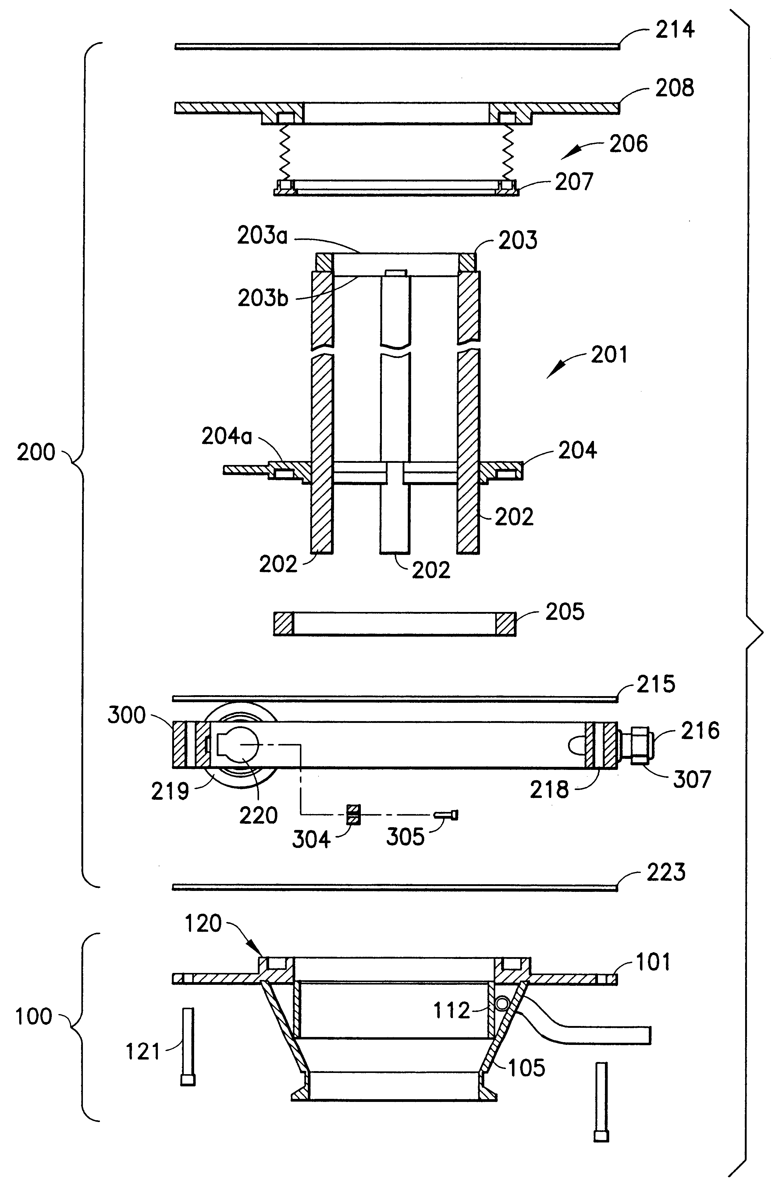
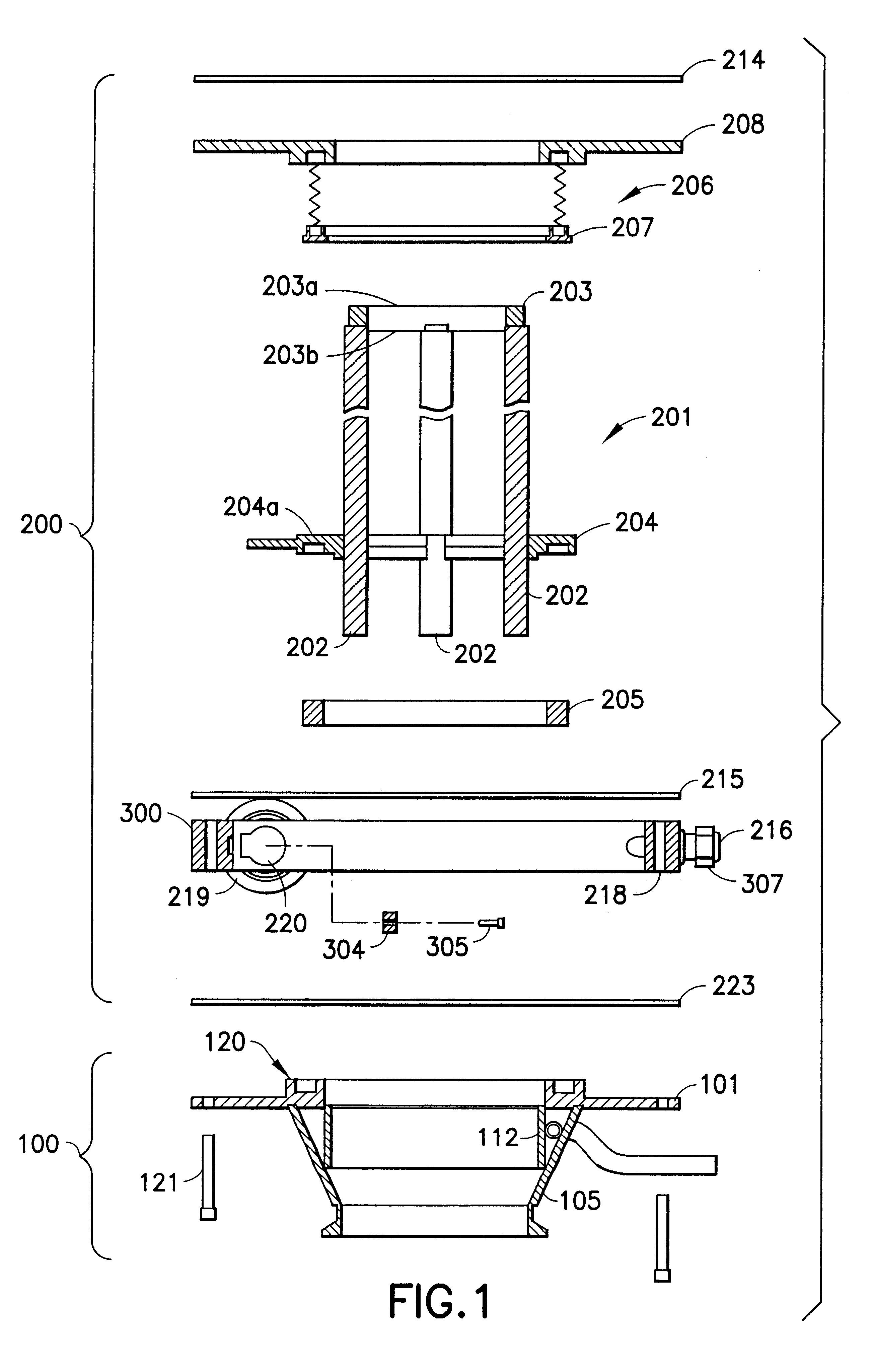
The present invention provides a new and improved RCCM and a new and improved water vortex. The RCCM and vortex aspects of the invention are suitably combined into one unit. FIG. 1 shows an expanded view of a combined RCCM / vortex apparatus of the present invention, including the water vortex unit 100 and the RCCM unit 200.

4.1 Water Vortex Unit

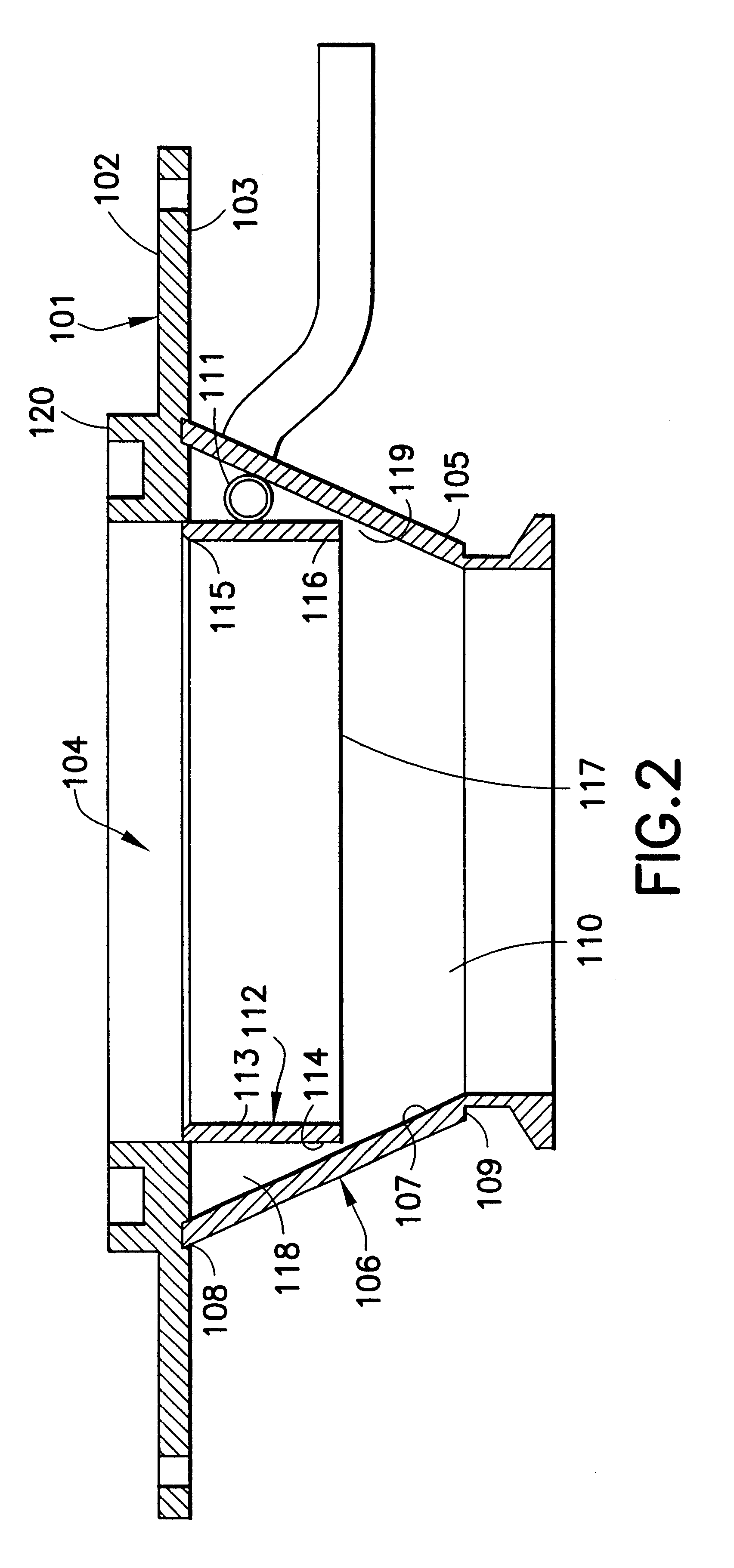
FIG. 2 shows an enlarged view of the water vortex unit 100. The water vortex unit generally comprises a top plate 101, a generally cone-shaped outer shell 105 and a baffle 112.

The top plate 101 comprises a top surface 102, a bottom surface 103 and a central opening 104.

The outer shell 105 comprises an outer surface 106, an inner surface 107, a top edge 108, a bottom edge 109 and a central opening 110 which is generally aligned with the central opening 104 of the top plate 101. The top edge 108 of the outer shell 105 is attached to and extends downwardly from the top plate 101. The diameter of the central opening 110 of the outer shell 105 narro...


PUM

PropertyMeasurementUnit
stroke lengthaaaaaaaaaa
pressureaaaaaaaaaa
lengthaaaaaaaaaa

Abstract

The present invention provides a reaction chamber cleaning apparatus comprising a chamber, a blade apparatus comprising at least one annular mounting member, at least four scraping blades attached peripherally about the annular mounting member, and a reciprocal movement unit for rotating said scraping blade(s) circumferentially back and forth along the interior surface of said chamber to scrape the interior surface of said chamber; said reaction chamber cleaning apparatus also comprising a vortex unit comprising a generally conical outer shell attached to and extending downwardly from the top plate top plate, and a liquid inlet arranged in relation to the outer shell to tangentially introduce liquid into the outer shell, thereby forming a laminar sheet of fluid on the inner surface of the outer shell; said vortex unit further comprising a baffle and a concentric chamber bounded by the outer surface of the baffle, the inner surface of the outer shell, and the bottom surface of the top plate. The invention also includes methods for using the reaction chamber for effluent abatement.

Description

1. BACKGROUND OF THE INVENTIONThe invention relates to a method and apparatus for cleaning a chamber.Chemical vapor deposition (CVD) processes, such as organometallic chemical vapor deposition (OMCVD or MOCVD) processes, are commonly employed in the semiconductor, optical, and optoelectronic industries for doping or coating a substrate. Certain chemical vapor deposition processes, particularly those associated with large scale fabrication of epitaxial semiconductor devices, produce highly toxic effluent gases, such as dichlorosilane, trichlorosilane, phosphine, arsine, and hydrogen and nitrogen derivatives which have been generated in the fabrication reactor. These toxic gaseous effluents are frequently contain particulate or particle-forming components, e.g., silica particles, which must be removed before the gases can be further processed, diluted and / or neutralized, prior to ultimate discharge into the ambient environment.Particulate-containing gaseous effluent is typically intro...

Claims


Application Information

Patent Timeline
Patent Type & Authority Patents(United States)
IPC IPC(8): B08B17/06B08B17/00B08B9/08C23C16/44F27D23/00F27D23/02B01J19/00B08B3/04B08B1/04F27D25/00H01L21/205
CPCB08B9/0808B08B17/06F27D25/001C23C16/4412C23C16/4407
Inventor INORI, DAVID M.
Owner APPLIED MATERIALS INC
Why Eureka
Try Eureka