Fuel evaporator

a fuel evaporator and fuel technology, applied in the direction of electrochemical generators, lighting and heating apparatus, separation processes, etc., can solve the problems of difficult to effectively inject liquid fuel fl, difficult to store or treat hydrogen gas or liquefied hydrogen gas, and output shortages

Inactive Publication Date: 2003-04-22
HONDA MOTOR CO LTD
View PDF12 Cites 14 Cited by
  • Summary
  • Abstract
  • Description
  • Claims
  • Application Information

AI Technical Summary

Problems solved by technology

However, as well known, it is not easy to store or treat hydrogen gas or liquefied hydrogen gas.
Also, it is difficult to inject the liquid fuel FL effectively to an area where the heat is concentrated in said evaporation chamber 111.
Further, it has been pointed as a defect that an output shortage is generated when load of the fuel cell system is increased.
When a liquid film is created from such liquefied state, the liquid film decreases the heat receiving area in comparison with liquid dropping condition and it becomes difficult to evaporate the liquid fuel.
In these cases, an excess fuel gas gradually evaporated from the liquid reservoir is naturally supplied to the fuel cell system, and even if amount of the liquid fuel to be supplied is decreased as the load of the fuel cell system is decreased, it becomes difficult to control the amount of the fuel gas to be exactly supplied.
Accordingly, the responsibility of the fuel cell system to output variation becomes worse.
Further, because of construction provided with the superheating chamber in the latter step of the evaporation chamber the passages of the combustion gas becomes complicated.
Such complicated combustion gas passages decrease heat efficiency of the combustion gas as the heat is deprived outside the apparatus.
It goes without saying that the heat efficiency of the combustion gas becomes poor.

Method used


Image

  • Fuel evaporator
  • Fuel evaporator
  • Fuel evaporator

Examples


Embodiment Construction

Now an example of fuel evaporator according to the present invention is explained with reference to the accompanying drawings.

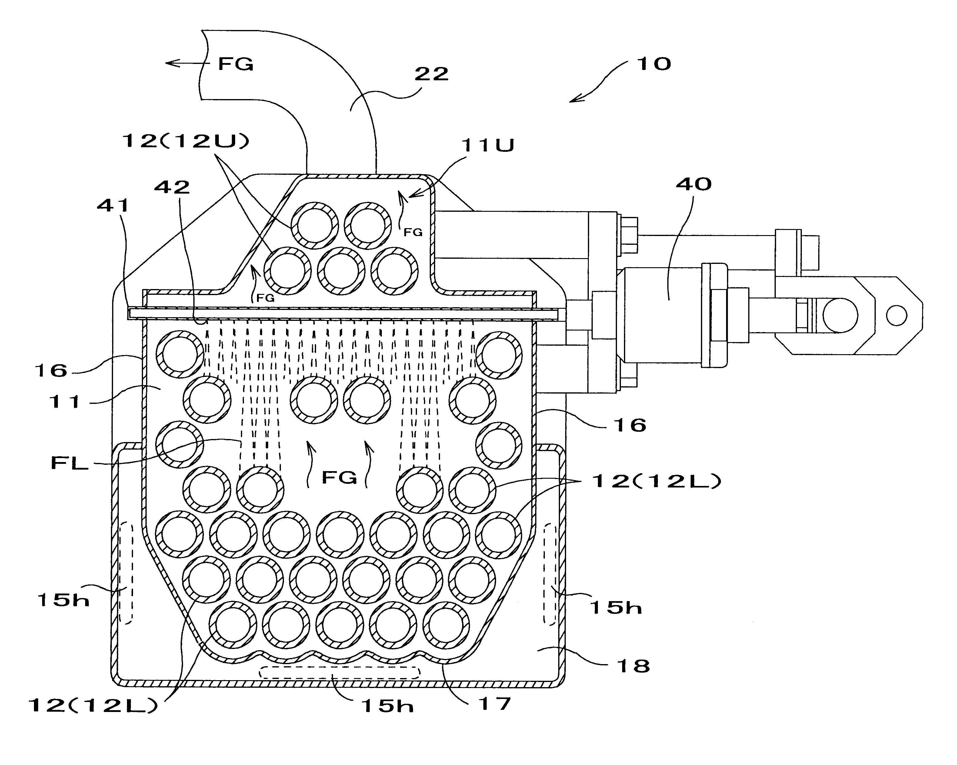
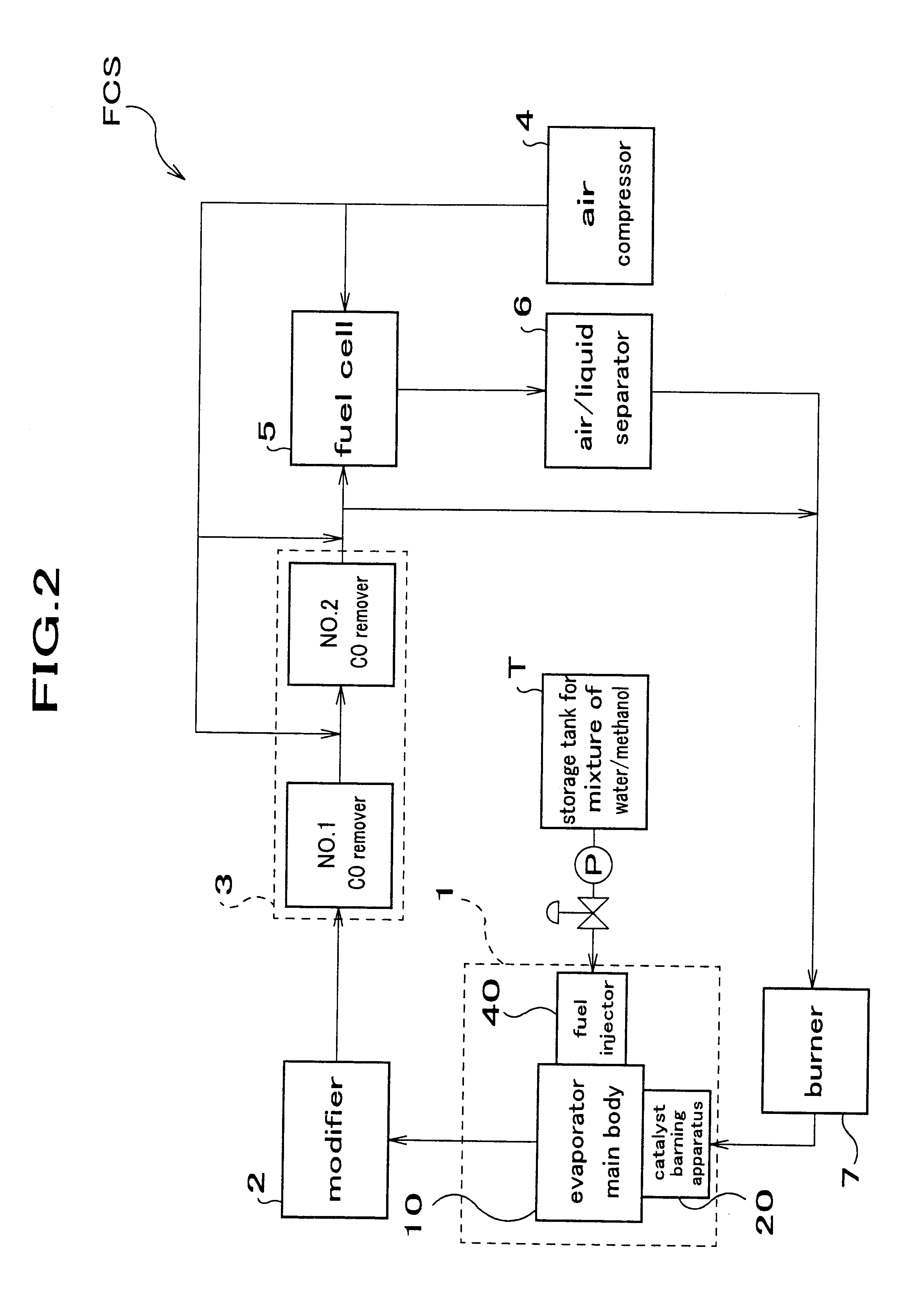
FIG. 2 is an outline of a fuel cell system applying a fuel evaporator according to the present invention. FIG. 3 is a cross section of a fuel evaporator according to the present invention. FIG. 4 is a cross section taken along A--A line in FIG. 3.

Reference code FCS indicates a fuel cell system. The fuel cell system comprises such that, as shown in FIG. 2, a fuel evaporator 1 to evaporate the liquid fuel which is a mixture of water and methanol supplied from a storage tank T by means of a transfer pump, a modifier 2 to modify the fuel gas with the aid of a reaction of a solid catalyst, a CO remover 3 provided to remove CO gas contained in modified gas exhausted from the modifier 2, said CO remover being comprised with No.1 and No.2 removers, a fuel gas acting as a high temperature heating medium containing hydrogen exhausted from the CO remover 3, and a fuel c...


PUM

PropertyMeasurementUnit
temperatureaaaaaaaaaa

Abstract

A fuel evaporator (1) includes an evaporation chamber (11) to prepare a fuel gas FG by evaporating a liquid fuel FL with heat, a fuel injector (40) to supply a liquid fuel to the evaporation chamber, a plurality of heating medium tubes (12) to lead a combustion gas HG through said evaporation chamber, a superheating part (11U) to heat a fuel gas FG evaporated in said evaporation chamber by means of the combustion gas HG, an exhaust duct (22) to exhaust the fuel gas FG, and a fuel injection tube (41). The fuel injection tube is provided with a plurality of injection holes (42), said fuel injection tube being extended into said evaporation chamber and said fuel injection tube is provided crossing at right angle with respect to a heating medium tube. Injection property of the fuel injection tube in said evaporation chamber is greatly improved. The liquid fuel is evaporated effectively and rapidly.

Description

1. Field of the InventionThe present invention relates to a fuel evaporator for a fuel cell system. More particularly, the present invention relates to a fuel evaporator to heat and evaporate a raw liquid fuel.2. Prior ArtIn recent years, it has come to our notice that a fuel cell system FCS is a power generator that causes less contamination in global environment. The fuel cell system is a system to take out an electric energy produced by a chemical reaction from a fuel gas with oxygen. The fuel gas such as hydrogen is supplied to a fuel cell together with an oxidized gas containing oxygen to produce an electric energy.However, as well known, it is not easy to store or treat hydrogen gas or liquefied hydrogen gas. For this reason, a modified gas is used as a fuel. The modified gas is prepared by evaporating a raw liquid fuel (hereinafter referred to only as liquid fuel) such as methanol by means of an evaporator.The applicant of the present invention has disclosed a fuel evaporator...

Claims


Application Information

Patent Timeline
Patent Type & Authority Patents(United States)
IPC IPC(8): B01B1/00B01D1/00B01D1/04C01B3/32C01B3/50C01B3/00H01M8/06F25B39/00H01M8/04H01M8/12
CPCB01B1/005B01D1/04C01B3/323C01B3/50H01M8/0631Y10S165/911C01B2203/0495Y02E60/324Y02E60/50C01B2203/047Y02E60/32
Inventor NAKAMURA, MASAHITOASANO, YUUJITOGASAWA, SHIYUUICHI
Owner HONDA MOTOR CO LTD
Why Eureka
Try Eureka