Method to determine optical proximity correction and assist feature rules which account for variations in mask dimensions

a technology of optical proximity correction and assist feature rules, which is applied in the field of correction of linewidth deviations in optical lithography, can solve the problems of inability to accurately represent the merit of a method, the cost of techniques, and the need for optical proximity correction

Inactive Publication Date: 2003-04-22
GLOBALFOUNDRIES U S INC
View PDF27 Cites 298 Cited by
  • Summary
  • Abstract
  • Description
  • Claims
  • Application Information

AI Technical Summary

Problems solved by technology

The difficulty with this method, however, is that the resulting process window is not a single number but instead a function typically given by depth of focus (DOF) as a function of exposure latitude (EL).
Various methods are used to reduce this function to a single figure of merit, but to this point no method has delivered a figure of merit that accurately represents the expected performance of a real process.
However, these techniques come at a cost: the need for optical proximity correction (OPC).
Therefore, this method may only account for a small subset of the systemic errors in the mask making or lithography process (e.g., nested-isolated bias) and can not account for any random errors in these processes.
Furthermore, these random errors may confound the correction rules.
Whereas, a common process window is computed by finding the overlap of two or more process windows, it suffers from the same drawbacks as an individual process window (namely, it is a function, not a single value, and it does not utilize real process information).

Method used


Image

  • Method to determine optical proximity correction and assist feature rules which account for variations in mask dimensions
  • Method to determine optical proximity correction and assist feature rules which account for variations in mask dimensions
  • Method to determine optical proximity correction and assist feature rules which account for variations in mask dimensions

Examples


Embodiment Construction

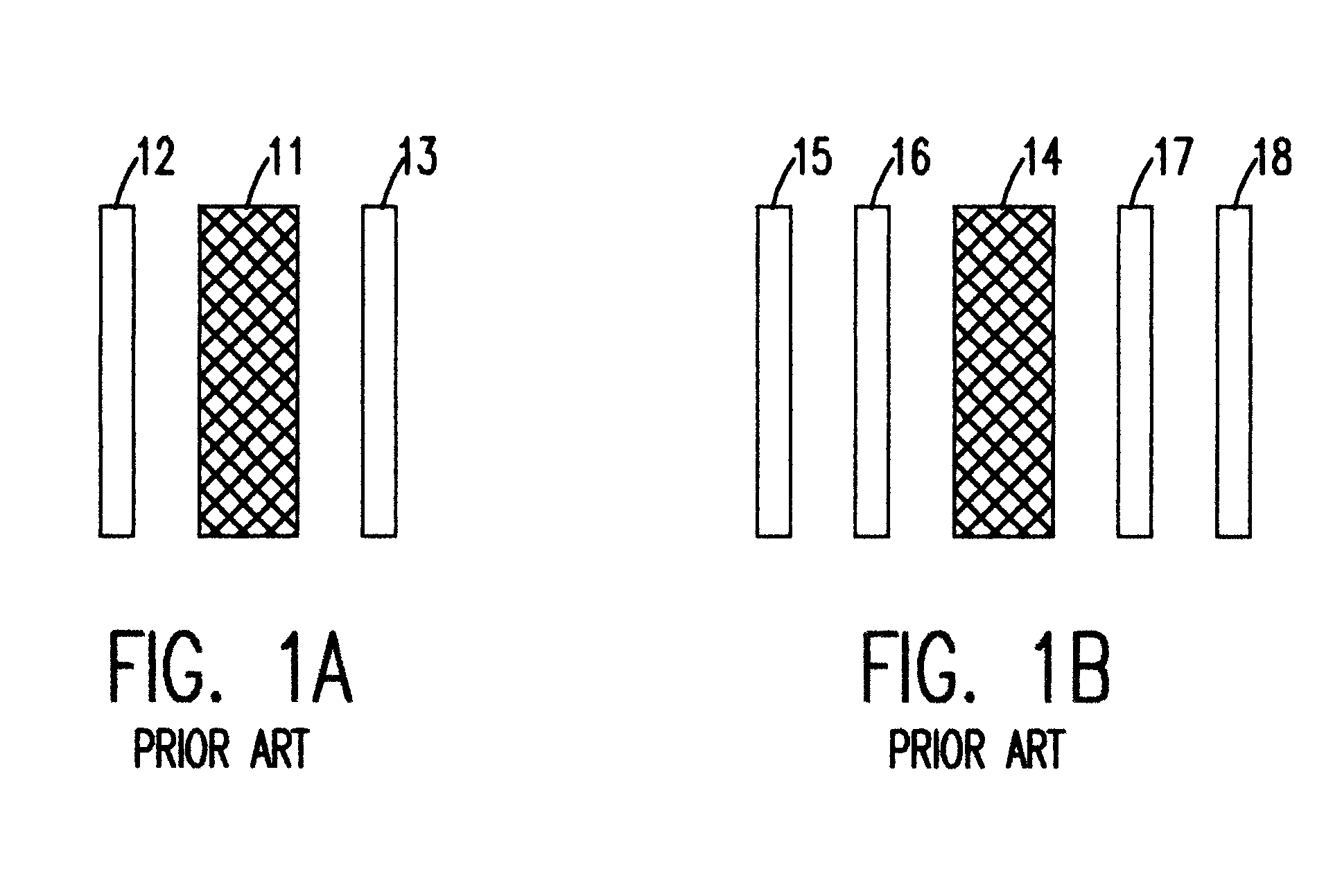
Referring now to the drawings, and more particularly to FIGS. 1A and 1B, there are shown mask patterns used in industry standard practice. FIG. 1A shows a line 11 with two fixed assist features 12 and 13 on either side of the line 11. FIG. 1B shows a line 14 with a pair of fixed assist features 15, 16 and 17, 18 on either side of the line 14. Industry standard practice is to use fixed assist feature sizes and placements with a maximum of two assists placed between two lines, or one per edge for an isolated line. The need for variable sizes and placements, along with multiple assist features (i.e., greater than two) is recognized, but generation of correction rules is difficult. For example, for pitches requiring 4 assists, there are at least 4 dimensions that can be varied. The result of this is that checking three values for each variable results in 3.sup.4 (3 to the fourth power) or 81 possible combinations.

Furthermore, the correction rule behavior tends to vary rapidly close to t...


PUM


Abstract

Optical proximity correction (OPC) and assist feature rules are generated using a process window (PW) analysis. A reference pitch is chosen and the mask bias is found that optimizes the process window. This can be done using standard process window analysis or through a weighted process window (WPW) analysis which accounts for focus and dose distributions that are expected in a real process. The WPW analysis gives not only the optimum mask bias, but also the center focus and dose conditions for the optimum process centering. A series of other pitches and mask biases are then analyzed by finding the common process window with the reference pitch. For the standard PW analysis, a common process window is found. For the WPW analysis, the WPW is computed at the center focus and dose conditions found for the reference pitch. If mask or lens errors are to be accounted for, then multiple structures can be included in the analysis. Once the common process windows for the mask features of interest have been computed, functional fits to the data can be found. Once the functional forms have been found for each of the OPC parameters, the rules table can be determined by solving for the spacings of interest in the design.

Description

1. Field of the InventionThe present invention generally relates to integrated circuit (IC) manufacture, and more particularly to the correction of line-width deviations in optical lithography systems used to print a pattern on a photoresist layer on a semiconductor wafer.2. Background DescriptionThere is a continuing effort to reduce the dimensions of integrated circuit (IC) devices, and this has required greater precision in the tools used to manufacture IC devices. IC devices are designed using computer-aided design (CAD) layout tools which allow chip manufacturers to plan the layout of the circuits on a semiconductor wafer. The finished designs must be transferred to the wafer in a manner that allows device features to be produced by various processes of etching, depositing, implanting, and the like. This is done by applying a photoresist layer to the surface of the wafer and then exposing the photoresist with radiation through a mask having a pattern of transparent and opaque a...

Claims


Application Information

Patent Timeline
Patent Type & Authority Patents(United States)
IPC IPC(8): G06F17/50
CPCG03F7/70441G03F1/36
Inventor LIEBMANN, LARS W.MANSFIELD, SCOTTWONG, ALFRED K.
Owner GLOBALFOUNDRIES U S INC
Why Eureka
Try Eureka