Trap apparatus

a trapping device and trapping technology, applied in the direction of vortex flow apparatus, liquefaction, machine/engine, etc., can solve the problems of clogging the filled layer of the discharged gas processing apparatus, failure of the vacuum pump, so as to increase the trapping efficiency, reduce equipment cost and running cost, and increase the service life of the vacuum pump

Inactive Publication Date: 2003-04-29
EBARA CORP
View PDF15 Cites 12 Cited by
  • Summary
  • Abstract
  • Description
  • Claims
  • Application Information

AI Technical Summary

Benefits of technology

The present invention has been made in view of the above drawbacks. It is therefore an object of the present invention to provide a trap apparatus which, in a film deposition process or the like, can increase the trapping efficiency while the n

Problems solved by technology

This tends to cause a failure of the vacuum pump.
However, while AlCl.sub.3 is being discharged under pressure, its partial pressure rises to cause AlCl.sub.3 to be deposited and attached to the inner wall of the vacuum pump, resulting in a failure of the vacuum pump.
However, it has been problematic in that a solid substance is deposited in the discharged gas processing apparatus disposed downstream of the vacuum pump, thereby clogging a filled layer in the discharged gas processing apparatus

Method used


Image

  • Trap apparatus
  • Trap apparatus
  • Trap apparatus

Examples


first embodiment

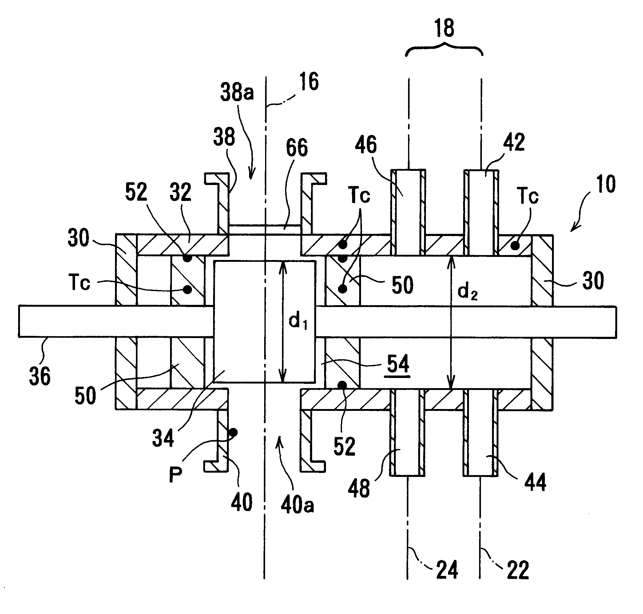
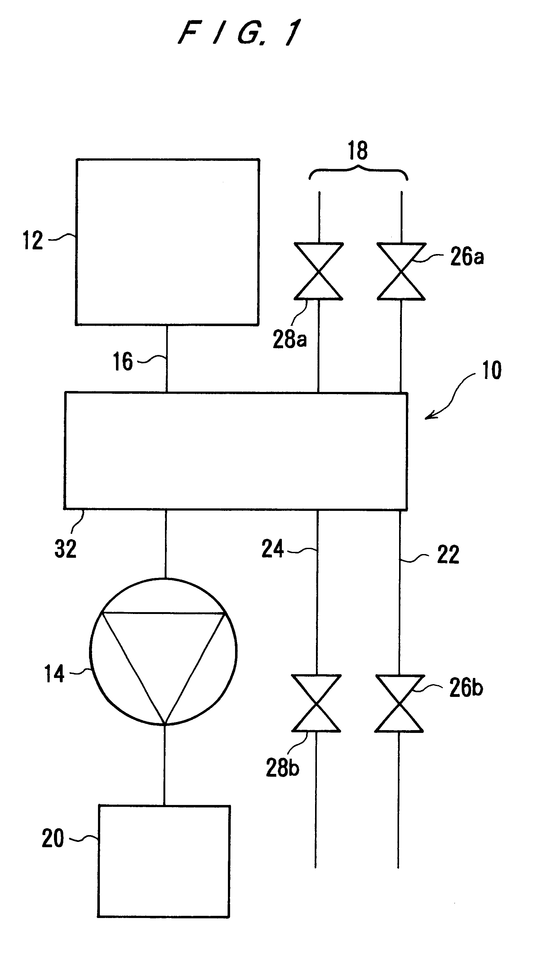
FIGS. 1 through 3 show a trap apparatus according to the present invention. The trap apparatus 10 is extended across a discharge path 16 for evacuating a hermetically sealed chamber 12 by a vacuum pump 14 and a regeneration path 18 disposed adjacent to the discharge path 16. In this embodiment, the vacuum pump 14 is a single stage vacuum pump. Alternatively, a multi-stage vacuum pump may be used. A discharged gas processing apparatus 20 for removing a toxic substance from the discharged gas is disposed downstream of the vacuum pump 14. The regeneration path 18 has a line 22 for a cleaning liquid and a line 24 for a drying gas. In the cleaning liquid line 22, control valves 26a and 26b are provided respectively on its introduction side and discharge side. In the drying gas line 24, control valves 28a and 28b are provided respectively on its suction side and discharge side.

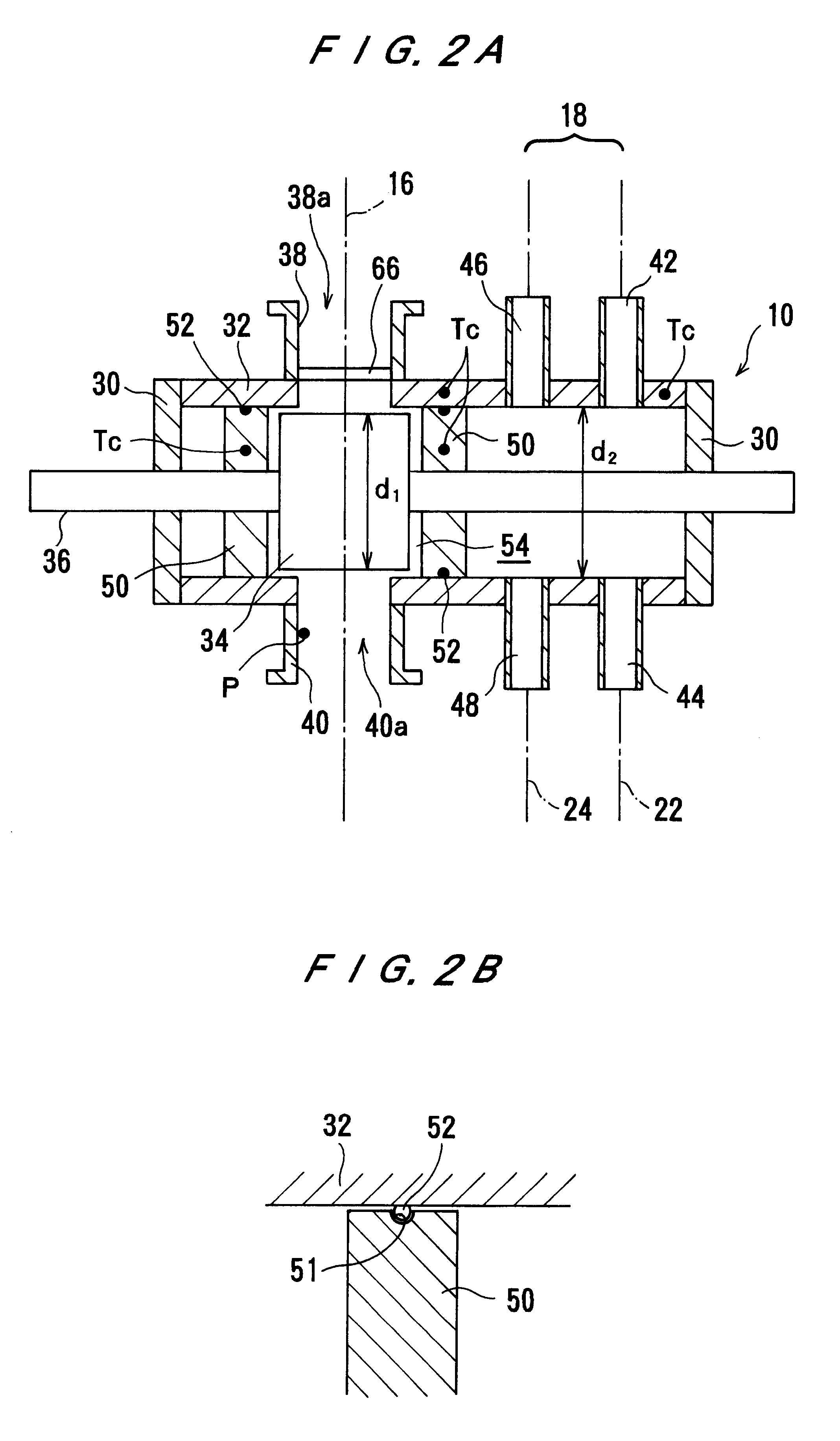
As shown in FIGS. 2A and 2B, the trap apparatus 10 comprises an approximately cylindrical trap container 32, both...

second embodiment

According to the present invention, the discharged gas which is discharged from the hermetically sealed chamber 12 flows into and through the trap container 32, and exits from the outlet 40a. At that time, the flow of the discharged gas is suppressed by the orifice (suppression section) 70. With the above arrangement, the discharged gas stays within the trap container 32 for a longer period of time. Further, in addition to the above-mentioned effect of increasing the proportion of discharged gas which flows through the trap passages 60a, 60b, 60c located on the center side and having good trapping efficiency, the effect of prolonging the time of contact of the discharged gas with the trap surface on the inner and outer surfaces of the baffle plates 58a, 58b, 58c in the trap unit 34 can further increase the trapping efficiency.

FIG. 5 shows a trap apparatus according to a third embodiment of the present invention. The trap apparatus comprises, instead of the orifice (throttle section)...

fourth embodiment

FIG. 6 shows a trap apparatus according to the present invention. In the trap apparatus 10, regeneration positions are provided on both sides of the discharge position in the trap container 32. The discharge path 16 is connected to the discharge position, and the regeneration paths 18 are connected to the two regeneration positions. The shaft 36 has two trap units 34, 34 and three valve elements 50, 50, 50 disposed respectively on the left side of the left trap unit 34, on the right side of the right trap unit 34, and between the trap units 34, 34. The sealing material 52 is mounted on the seal mounting groove 51 (see FIG. 2B) provided on the outer circumferential surface of each of the valve elements 50. Thus, the three valve elements 50, 50, 50 and the inner wall of the trap container 32 define two trap / regeneration chambers 54, 54 each hermetically sealed by the sealing materials 52.

In this embodiment, a cleaning liquid line 22 having control valves 26a, 26b joins a drying gas li...


PUM

PropertyMeasurementUnit
Flow rateaaaaaaaaaa
Shapeaaaaaaaaaa

Abstract

A trap apparatus includes a discharge path for evacuating a hermetically sealed chamber through a vacuum pump, a hermetically sealed trap container extended across the discharge path and a regeneration path disposed adjacent to the discharge path, a trap unit disposed in the trap container for attaching a product in a discharged gas thereon and removing the product form the discharged gas, the trap unit being selectively located at the discharge path or the regeneration path, a valve element disposed on both sides of the trap unit and being movable integrally with the trap unit, and a sealing material mounted on an outer circumferential surface of the valve element so as to slide over an inner circumferential surface of the trap container when the trap unit is moved.

Description

BACKGROUND OF THE INVENTION1. Field of the InventionThe present invention relates to a trap apparatus for use in an evacuating system for evacuating a vacuum chamber for a semiconductor fabrication apparatus or the like.2. Description of the Related ArtA conventional evacuating system will be described below with reference to FIG. 16. In FIG. 16, a hermetically sealed chamber 201 comprises a process chamber for use in a semiconductor fabrication process such as an etching apparatus or a chemical vapor deposition (CVD) apparatus. The hermetically sealed chamber 201 is connected to a vacuum pump 203 through a discharge path 202. The vacuum pump 203 serves to increase the pressure of gases discharged from the process in the hermetically sealed chamber 201 to the atmospheric pressure. An oil-sealed rotary vacuum pump has heretofore been used as the vacuum pump 203. A dry pump is mainly used as the vacuum pump 203 at present.If the degree of vacuum required by the hermetically sealed cha...

Claims


Application Information

Patent Timeline
IPC IPC(8): B01D53/34B01D53/02B01D53/14B01D8/00C23C16/44H01L21/205
CPCB01D8/00B01D53/02C23C16/4412B01D53/34B01D53/14
Inventor NOMURA, NORIHIKO
Owner EBARA CORP
Why Eureka
Try Eureka