Glare-resistant touch panel

a touch panel and glare-resistant technology, applied in the field of glare-resistant touch panels, can solve the problems of deformation decreased operability of the touch panel, and increased the amount of outward bulge of the top sheet member

Inactive Publication Date: 2003-05-06
GUNZE LTD +1
View PDF13 Cites 35 Cited by
  • Summary
  • Abstract
  • Description
  • Claims
  • Application Information

AI Technical Summary

Benefits of technology

Since the second sheet member has the polarizing property, the touch panel is guarded against glare. When such a touch panel is mounted on the front of a display panel such as an LCD panel, the visibility of the content displayed on the display panel is improved. Also, even when the second sheet member and the third sheet member contract in a high ambient temperature, after the ambient temperature returns to normal the third sheet member will not become slack against the second sheet member, because the thermal contraction rate of the third sheet member is equal to or larger than that of the second sheet member underneath it. Hence the outward bulge of the touch panel is effectively suppressed, and its appearance and operability is maintained regardless of temperature variations.
Here, the third sheet member may have a lower thermal linear expansion coefficient than the second sheet member. Even when the second sheet member is expanding to bulge outward as the ambient temperature rises, the third sheet member with the lower thermal linear expansion coefficient serves to suppress such an outward bulge of the second sheet member, so that the distance between the first and second sheet members will not widen substantially. As a result, the appearance and operability of the touch panel can be maintained regardless of temperature variations.
Here, the second sheet member and the third sheet member may be adhered with an adhesive that has a stress relieving property. The adhesive layer formed as such can absorb thermal stress growing between the second and third sheet members at elevated temperatures. Accordingly, no deviation from alignment will occur between the second and third sheet members, so that the operability of the touch panel can be maintained. Here, the viscoelasticity of the stress relieving adhesive is preferably in a range of 1.0.times.10.sup.5 dyn / cm.sup.2 to 1.2.times.10.sup.6 dyn / cm.sup.2. Also, the third sheet member may be coated with a hard coating material on its surface which is to be adhered to the second sheet member. In so doing, the adhesion of the third sheet member with the stress relieving adhesive is strengthened, which improves the durability of the touch panel.
Here, the third sheet member may have a lower hygroscopic linear expansion coefficient than the second sheet member. Even when the second sheet member is expanding to bulge outward due to moisture absorption, the third sheet member with the lower hygroscopic linear expansion coefficient serves to keep the second sheet member from bulging outward. Thus, the outward bulge of the touch panel due to moisture absorption can be effectively suppressed.

Problems solved by technology

This large difference in thermal linear expansion coefficient between the top and base sheet members causes the following problems.
As the temperature rises, the whole top sheet member including the polarizer bulges outward, thereby seriously deforming the touch panel.
Besides, the operability of the touch panel decreases, as the space between the top and base sheet members widens and forces the user to apply a greater pressure to operate the touch panel.
Given the recent trend toward larger touch panels with upsizing of LCD panels, the amount of outward bulge of the top sheet member is likely to increase, which will further degrade the touch panel's operability.
.), the touch panel bulged upward and became seriously deformed, resulting in poor operability.
If a car navigation system equipped with a touch panel is left in such a hostile condition, the top sheet member of the touch panel will bulge upward greatly, causing a significant decrease in operability.

Method used


Image

  • Glare-resistant touch panel
  • Glare-resistant touch panel
  • Glare-resistant touch panel

Examples


Embodiment Construction

)

The following is a description on a touch panel according to an embodiment of the present invention, with reference to the figures.

(General Construction of a Touch Panel 100)

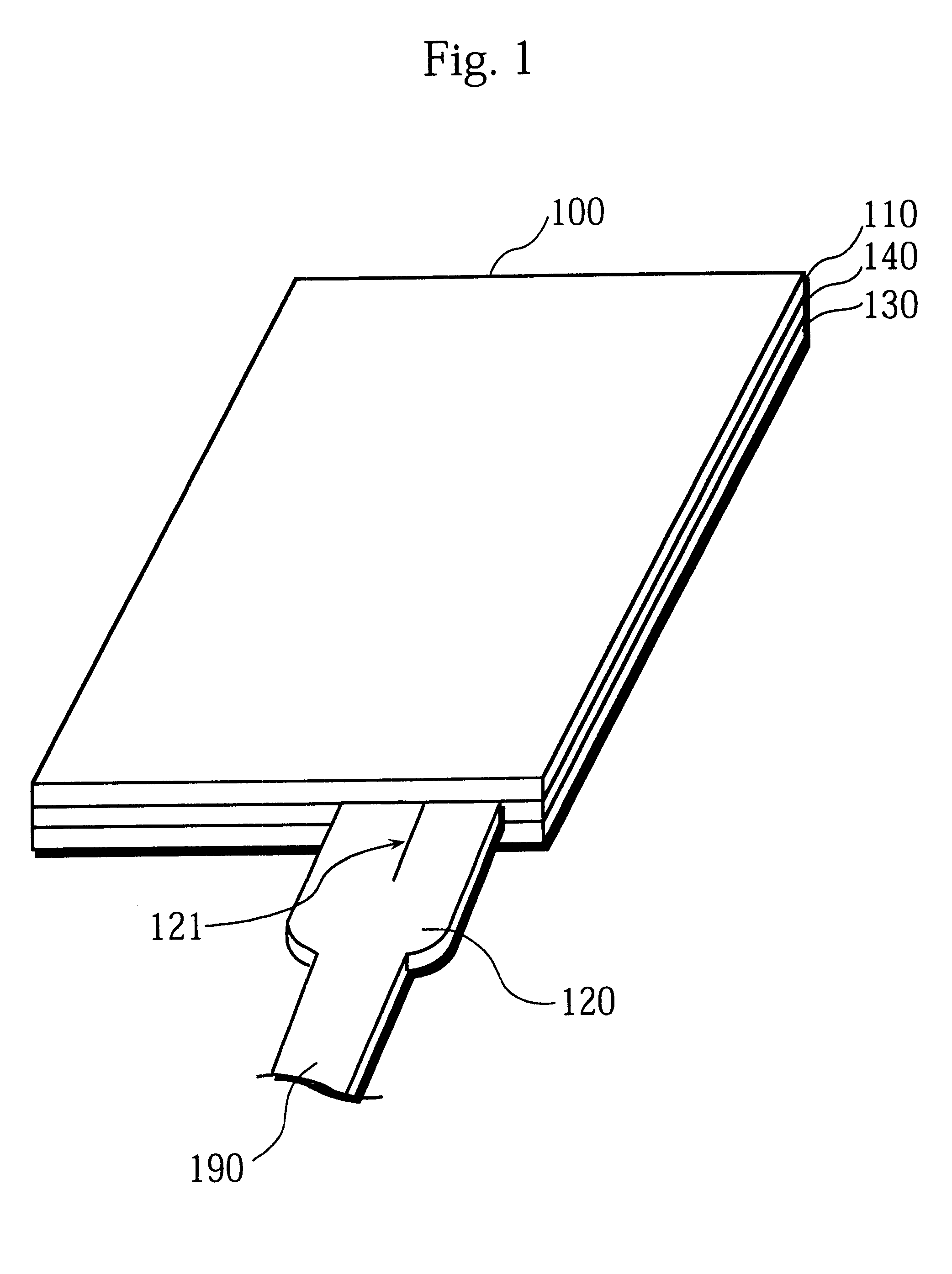
FIG. 1 is a perspective view of a touch panel 100 according to the embodiment of the invention.

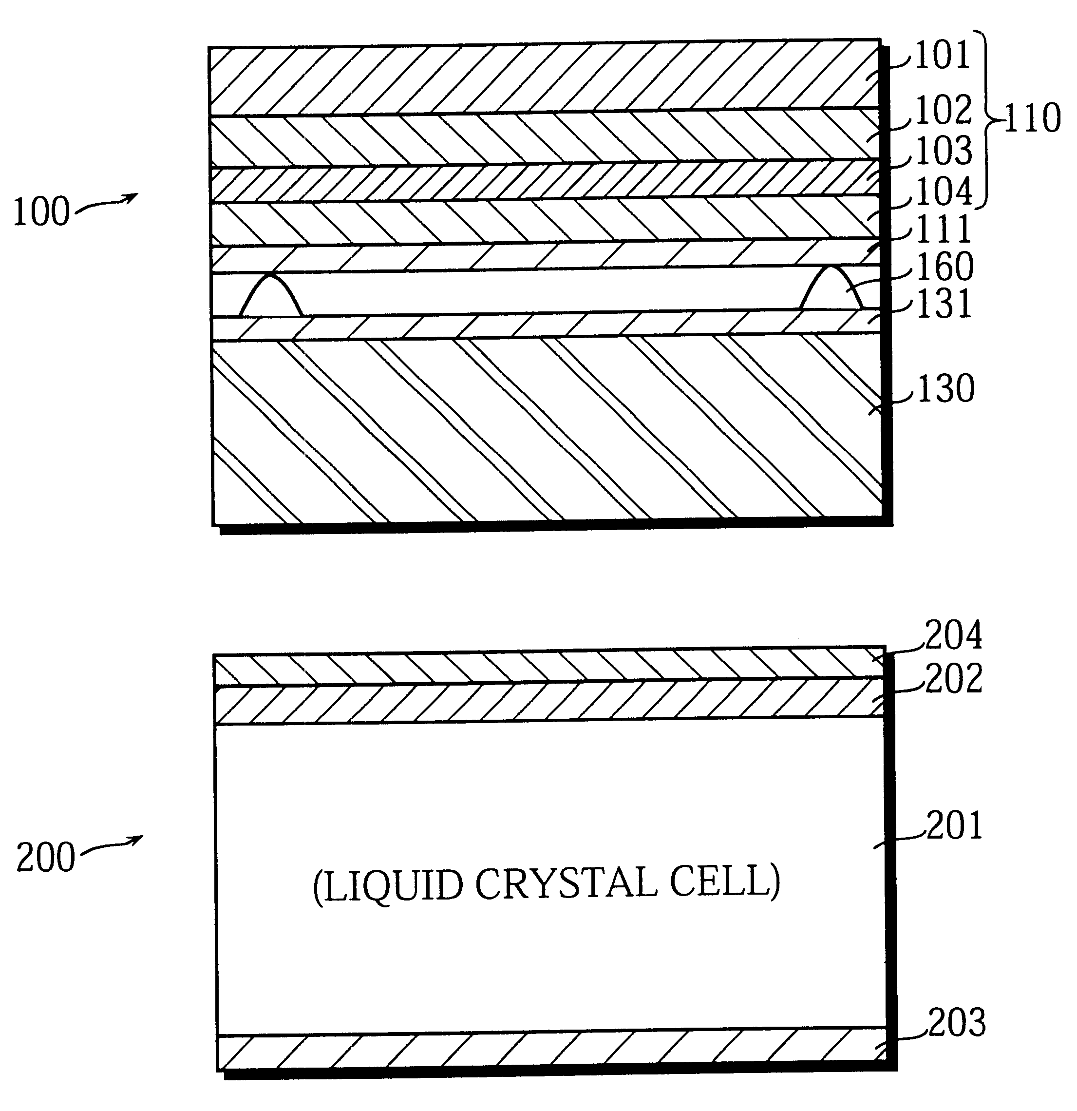
As illustrated, the touch panel 100 is constructed by laminating a top sheet member 110 and a base sheet member 130 with a spacer 140 being placed therebetween.

The top sheet member 110 is a flexible, transparent sheet member for receiving user input made with a finger or an input pen, and is made by laminating a plurality of resin films (described later). Reference numeral 120 is a connector unit that is connected to electrodes inside the touch panel 100.

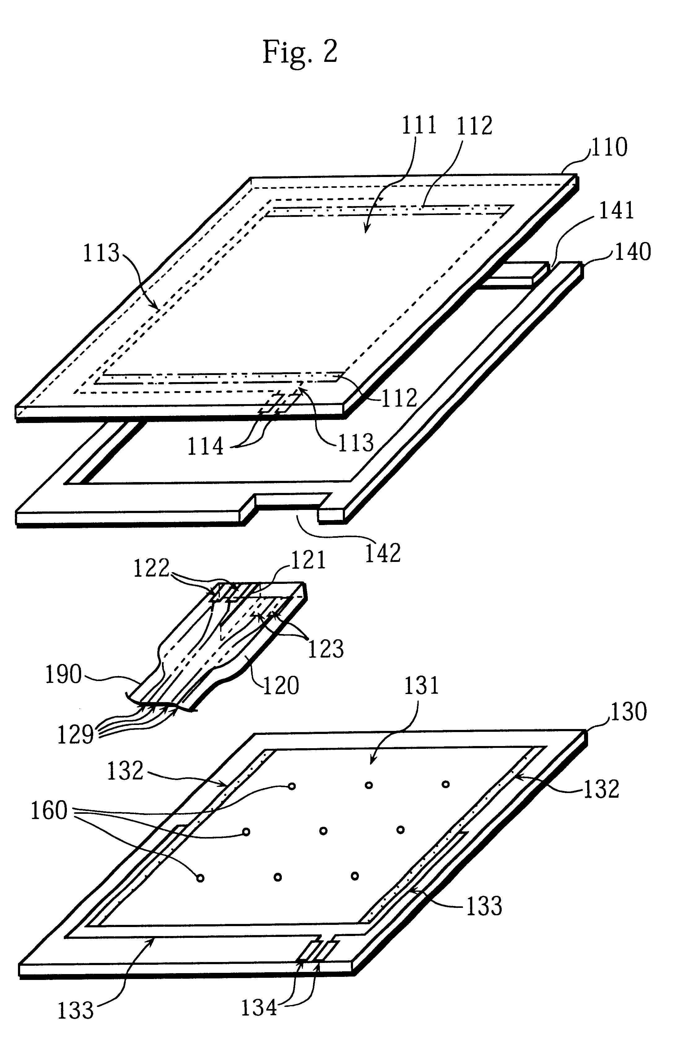
FIG. 2 is an exploded view of the touch panel 100 shown in FIG. 1.

In the FIGURE, the spacer 140 has a shape of a picture frame except for a clearance 141. The spacer 140 is made of a PET film or the like. An adhesive is applied to both upper and lower sides of the spa...


PUM

PropertyMeasurementUnit
angleaaaaaaaaaa
temperatureaaaaaaaaaa

Abstract

A touch panel is constructed of a top sheet member having a resistive membrane on its inner surface and a base sheet member having a resistive membrane on its inner surface, the top and base sheet members facing each other with dot spacers being located in between. The top sheet member is formed by laminating a bulge-resistant film, a polarizing plate, a quarter wavelength plate, and a light isotropic film in this order from above. A PET film which is not heat-treated so as to have a higher thermal contraction rate than the other members of the top sheet member underneath such as the polarizing plate, is used as the bulge-resistant film. Since the bulge-resistant film contracts more than the polarizing plate under a high ambient temperature, after the ambient temperature returns to normal, the bulge-resistant film does not become slack against the polarizing plate. Accordingly, the top sheet member can be kept from bulging outward.

Description

1. Field of the InventionThe present invention relates to a glare-resistant touch panel, and more particularly relates to a technique for improving the operability of the touch panel in use environments that involve relatively high temperatures.2. Description of the Related ArtA typical touch panel is constructed of an ultrathin glass plate (base sheet member) and a flexible transparent resin film (top sheet member) that are set facing each other and have resistive membranes respectively on their opposed surfaces, with spacers being placed in between the two sheet members in order to provide a certain spacing.With an ever-widening range of applications of such touch panels, the demand for products that provide new additional values is growing in recent years. As an example, for combined use with a liquid crystal display (LCD) panel equipped in an outdoor-use device such as a car navigation system, a glare-resistant touch panel which is coated with a film of polarizer on its surface ...

Claims


Application Information

Patent Timeline
Patent Type & Authority Patents(United States)
IPC IPC(8): G06F3/033G06F3/041G02F1/1333G02F1/1335G06F3/045
CPCG06F3/045
Inventor MURAKAMI, YUKIOHIRANO, SHUNSUKEMINAKUCHI, KEIICHI
Owner GUNZE LTD
Why Eureka
Try Eureka