Integrated frequency translation and selectivity with a variety of filter embodiments

Inactive Publication Date: 2003-05-06
PARKER VISION INC
View PDF517 Cites 97 Cited by
  • Summary
  • Abstract
  • Description
  • Claims
  • Application Information

AI Technical Summary

Problems solved by technology

In fact, generally, high Q factors at high frequencies are difficult to realize using conventional filter techniques, and have at best limited tuning capabilities.
Some of these spurious components 404 may

Method used


Image

  • Integrated frequency translation and selectivity with a variety of filter embodiments
  • Integrated frequency translation and selectivity with a variety of filter embodiments
  • Integrated frequency translation and selectivity with a variety of filter embodiments

Examples


first embodiment

3.3.1 Band Pass Filtering and Frequency Translation

3.3.1.1 Operational Description

3.3.1.2 Structural Description

second embodiment

3.3.2 Low Pass Filtering and Frequency Translation

3.3.2.1 Operational Description

3.3.2.2 Structural Description

third embodiment

3.3.3 Filtering With Mid-Point Injection and Frequency Translation

3.3.3.1 Operational Description

3.3.3.2 Structural Description

3.3.4 Fourth Embodiment: Finite Impulse Response (FIR) Filtering

3.3.5 Fifth Embodiment: Running Average Filter

3.3.6 Sixth Embodiment: N-Path Filter

3.3.7 Seventh Embodiment: Passive Filter

3.3.8 Other Embodiments

3.4 Implementation Examples

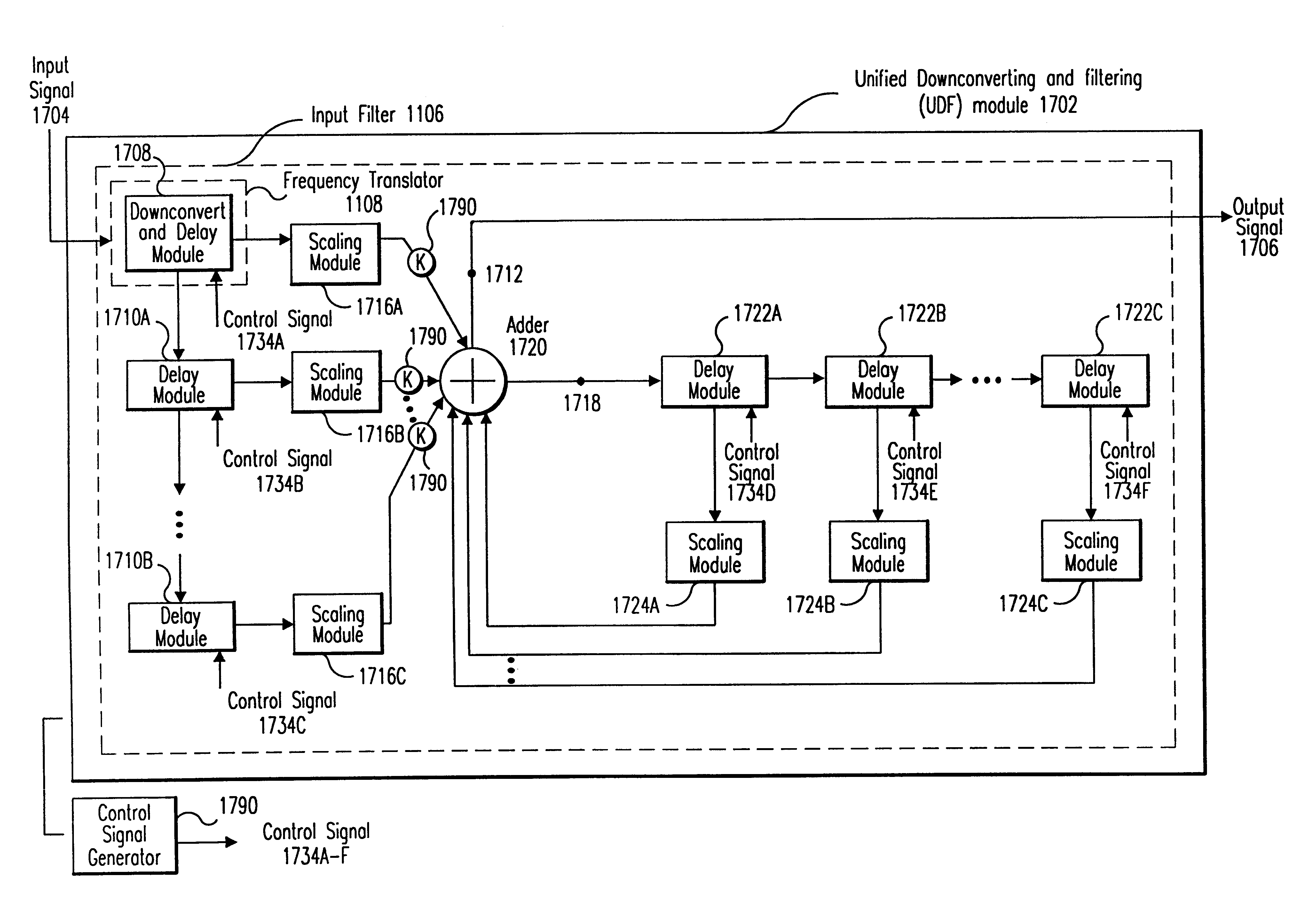
3.4.1 Implementation Example of a Unified Downconverting and Filtering (UDF) Module

3.4.2 Implementation Examples of Components of the UDF Module

3.4.2.1 Downconvert and Delay Module

3.4.2.1.1 Universal frequency down-conversion (UFD) Module

3.4.2.2 Delay Modules

3.4.2.3 Scaling Modules

3.4.2.4 Adder

3.4.2.5 Control Signal Generator

3.4.2.6 Output Sample and Hold Module

3.4.2.7 Output Smoothing Module

3.4.2.8 Mid-Point Injection Embodiment: High Frequency Delay Module

3.4.2.9 Mid-Point Injection Embodiment: Optional Filter

3.4.2.10 Mid-Point Injection Embodiment: Downconvert Module

3.4.2.11 Mid-Point Injection Embodiment: Upconvert Modul...


PUM


Abstract

Methods and apparatuses for frequency selectivity and frequency translation, and applications for such methods and apparatuses, are described herein. The method includes steps of filtering an input signal, and down-converting the filtered input signal. The filtering and the down-conversion operations are performed in an integrated, unified manner. The apparatus described herein can be implemented as an integrated circuit (IC).

Description

1. Field of the InventionThe present invention is generally related to methods and apparatuses for frequency translation and frequency selectivity.2. Related ArtFIG. 1 is a block diagram of an example conventional receiver 112. FIG. 2 is a flowchart representing the operation of the receiver 112.In step 206, a band-select filter 102 filters an RF (radio frequency) spectrum 114. An example RF spectrum 114 is shown in FIG. 4A. The RF spectrum 114 includes signal components at frequencies f.sub.1, f.sub.2, f.sub.3, and f.sub.4. Assume, for purposes of example, that the receiver 112 is configured to receive signals at frequency f.sub.3.Typically, the band-select filter 102 is a wide-band filter. The characteristics of the band-select filter 102 are generally illustrated in FIG. 4B. The band-select filter 102 has a center frequency f.sub.c, and a band-select bandwidth 402. In the example shown in FIG. 1, where the receiver 112 is receiving an RF spectrum 114, the center frequency f.sub.c...

Claims


Application Information

Patent Timeline
IPC IPC(8): H03D7/00H04B7/12H04B7/02
CPCH04B7/12H03D7/00
Inventor COOK, ROBERT W.BULTMAN, MICHAEL J.LOOKE, RICHARD C.MOSES, JR., CHARLEY D.SORRELLS, DAVID F.
Owner PARKER VISION INC
Why Eureka
Try Eureka