

Angle detector
a detector and angle technology, applied in the field ofangle detectors, can solve the problems of increasing the difficulty of obtaining a required performance, increasing the difficulty of securing the installation space, and increasing the difficulty of securing the required performance, so as to reduce the dimensional restriction and improve the performan
- Summary
- Abstract
- Description
- Claims
- Application Information
AI Technical Summary
Benefits of technology
Problems solved by technology
Method used
Image

Examples
first embodiment
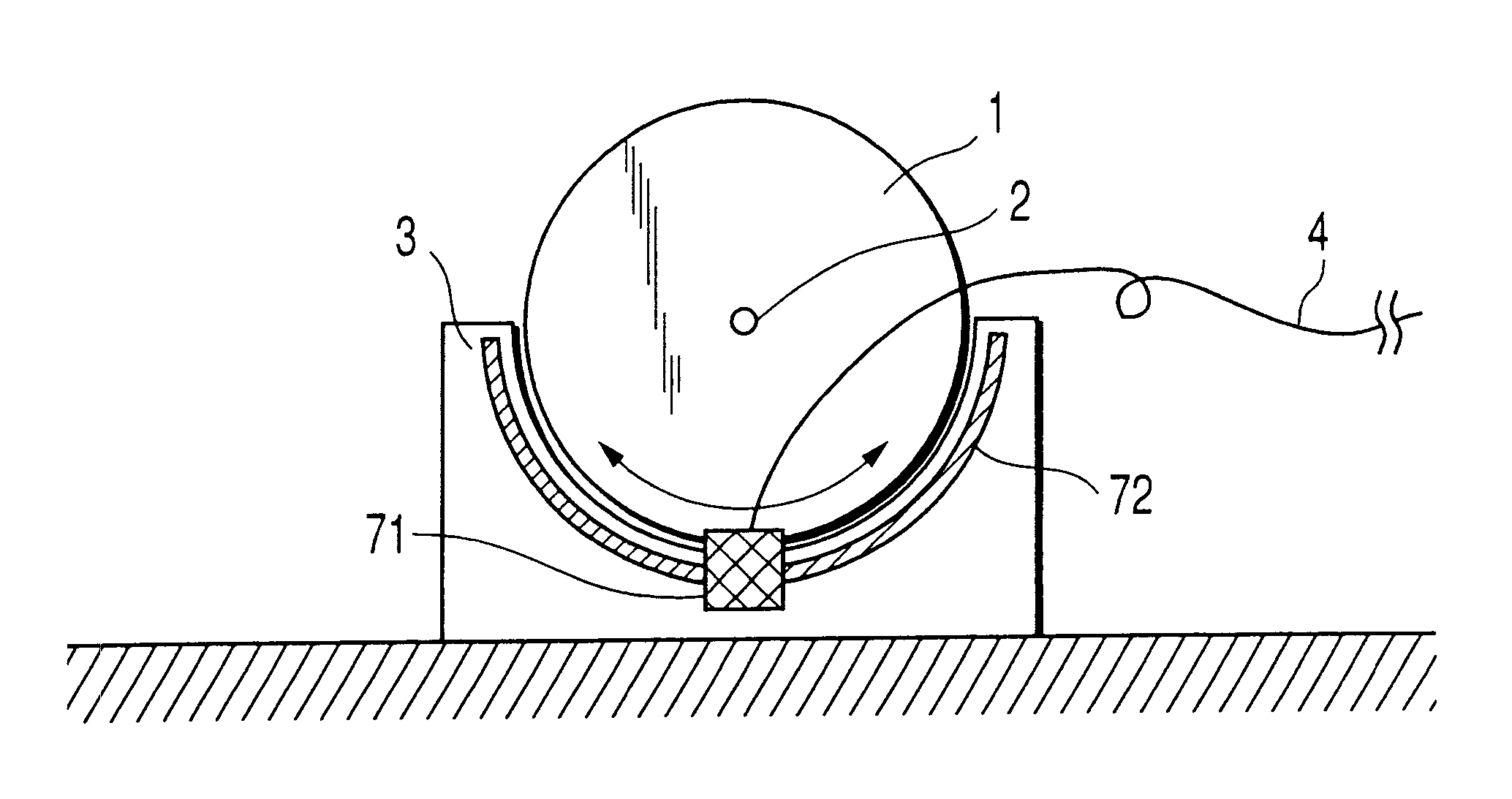
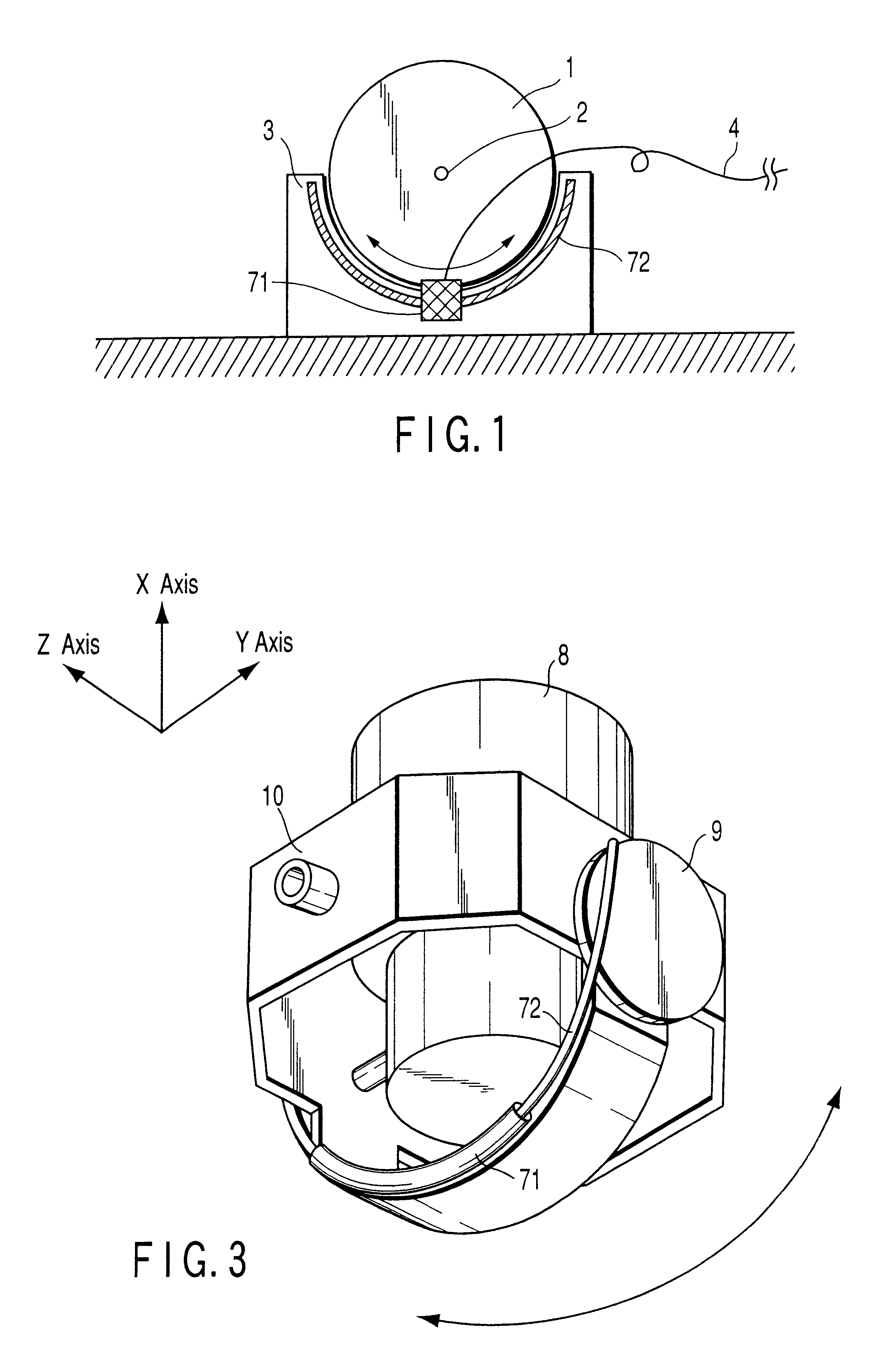
FIG. 1 is a view showing a structure of an angle detector according to the present invention. The angle detector shown in FIG. 1 includes a sensor head 71 and rod 72. The sensor head 71 is mounted to a rotating body 1 adapted to be rotated about a rotating shaft 2. The rod 72 is mounted on a fixing member 3 provided in a separating relation from the rotating body 1.
With the rotation of the rotating body 1, the sensor head 71 is moved along the rod 72. A connection line 4 is attached to the sensor head 71 and adapted to supply a drive voltage to the sensor head 71 and take out a detection signal corresponding to a rotation signal.
One feature of the above-mentioned structure lies in that the rod 72 is formed to have an arc-like configuration along the moving locus of the sensor head 71. It is preferable that the sensor head 71 and rod 72 have the same curvature radius.
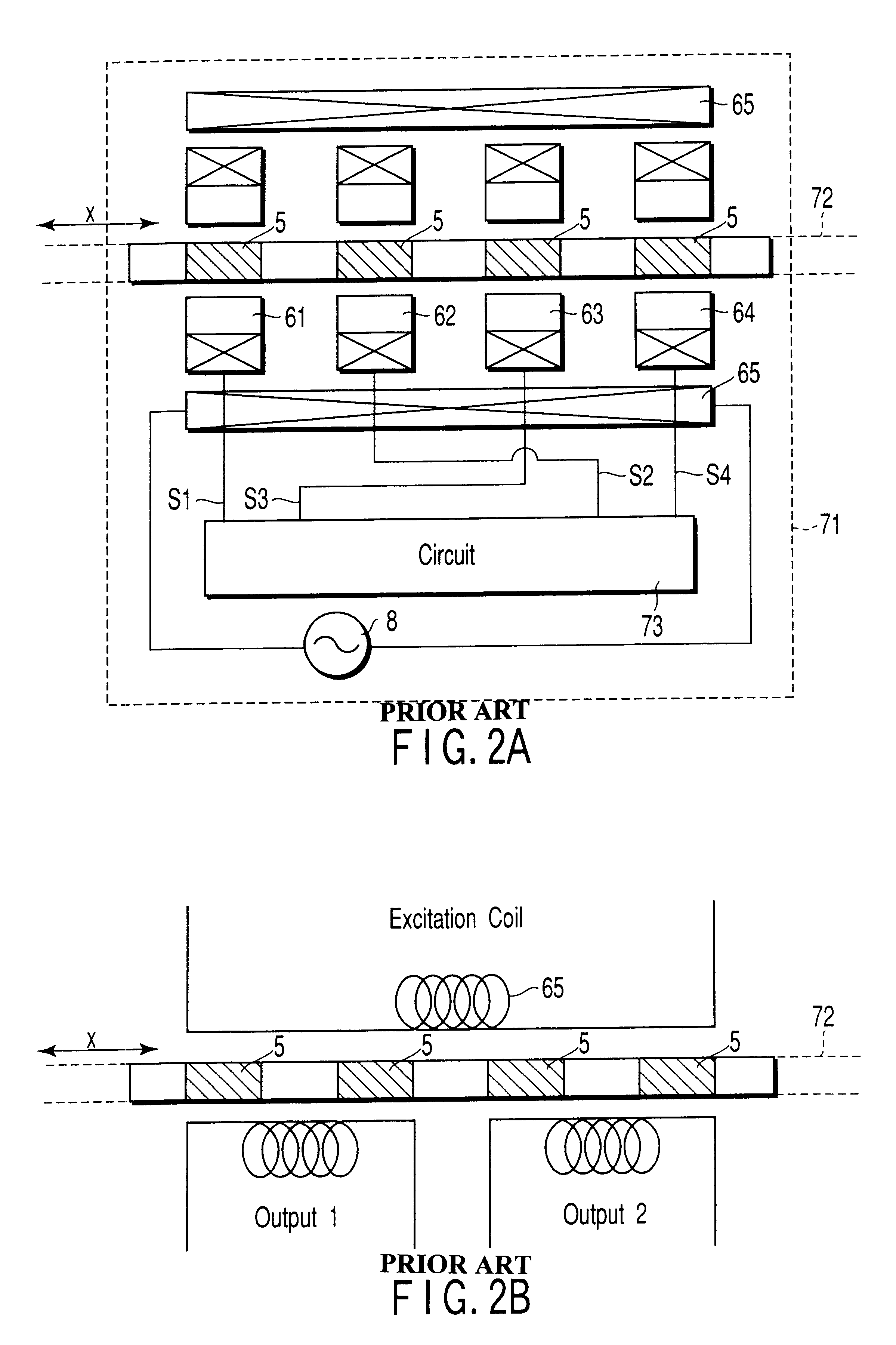
FIG. 2 is a view for generally explaining the principle of a straight line type position detector. In FIG. 2(A) and FI...
second embodiment
FIG. 4 is a view showing an angle detector according to the second embodiment of the present invention. In FIG. 4, a rod 72 is mounted on one side of a rotating body 1. A sensor head 71 is mounted to a fixing member 3. The rod 72 has its length set to be able to cover the operation range of the rotating body 1 and is preferably mounted on the edge of the rotating body 1.
When, in the above-mentioned arrangement, the rotating body 1 is rotated, the rod 72 is moved. Since the sensor head 71 is fixed, a relative movement between the sensor head 71 and the rod is made with the rotation of the rotating body 1. By doing so, it is possible to detect the rotation angle of the rotating body 1.
According to the above-mentioned embodiment, it is possible to obtain not only the advantages of the first embodiment but also further advantages set out below. In FIG. 4, the sensor head 71 is mounted on the fixing member 3 and, for this reason, there is no risk that a connection line 4 will provide a b...
third embodiment
FIG. 5 is a view showing a structure of an angle detector according to a third embodiment of the present invention. The angle detector shown in FIG. 5 is of such a type that the length of a rod 72 mounted on a rotating body 1 is made to correspond to one pitch, that is, a length substantially corresponding to a width of a sensor head 71. In this case, a plurality of sensor heads 71 are mounted on a fixing member 3. The operation range of the rotating body 1 is covered by the plurality of sensor heads.
In the above-mentioned structure, the sensor head 71 generates an output, when the rod 72 is moved to face it, that is, the output of the sensor head 71 is made selectively effective and used for the detection of the rotation angle of the rotating body. Further, the measuring range of the angle detection is secured over a plurality of pitches.
In the structure shown in FIG. 4, a necessary angle measuring range is obtained by making the rod 72 longer, while, in the structure shown in FIG....
PUM
 Abstract
Description
Claims
Application Information