Fill up tool and mud saver for top drives

a technology of filling tool and top drive, which is applied in the direction of drilling pipe, drilling casing, and accessories for wells, etc., can solve the problems of high cost, time-consuming and therefore expensive, of top drive threads

Inactive Publication Date: 2003-06-03
HALLIBURTON ENERGY SERVICES INC
View PDF48 Cites 92 Cited by
  • Summary
  • Abstract
  • Description
  • Claims
  • Application Information

AI Technical Summary

Benefits of technology

A specific object of the present invention is to provide a tool for use in a top drive drilling system that accommodates return flow of well fluids from a casing string being installed with a drill string and that prevents leakage of fluid from the top drive and associated piping when the top drive is separated from the drill string while selectively permitting forward pumping circulation through the top drive and drill string as the drill string and casing are being lowered into the well.
It is also an object of the present invention to provide a fill up tool that permits the safe running of subsea completion strings and casing liners from drilling rigs using a top drive unit while maintaining minimal drilling fluid loss and greatly reducing adverse environmental impact.

Problems solved by technology

The requirement to repeatedly make up and disengage the top drive threads, however, is time consuming and therefore expensive, particularly in offshore installations.

Method used


Image

  • Fill up tool and mud saver for top drives
  • Fill up tool and mud saver for top drives
  • Fill up tool and mud saver for top drives

Examples


Embodiment Construction

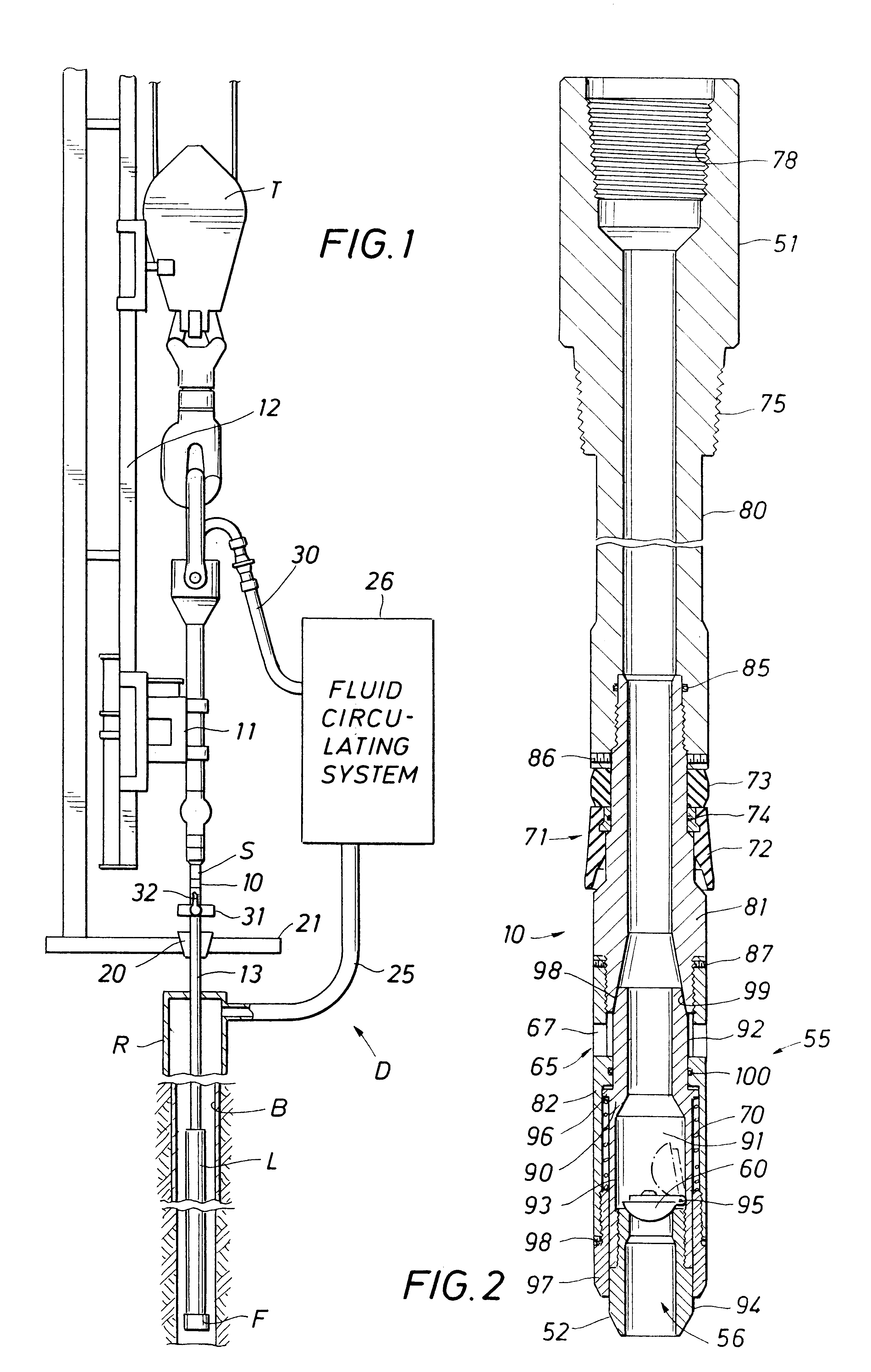
FIG. 1 illustrates a top drive fill up and mud saver tool of the present invention, indicated generally at 10, included as part of an offshore drilling system, indicated generally at D. The drilling system D is equipped with a top drive 11 supported for vertical movement along a torque track 12 in a conventional manner. The top of the tool 10 connects to the top drive through a saver sub S.

The tool 10 is illustrated connected to the top of a drill string 13, which is supported by slips 20 from a floor 21 of the drilling system D. The drill string 13 supports a casing liner L being run into a well bore B. An automatic fill up shoe F at the bottom of the liner L automatically opens to allow drilling fluids in the bore to flow into the liner. A well pipe, which may be a riser R, extends from the wellbore B to return fluid in the wellbore into a returns line 25 that connects with the system's fluid circulating system 26. The circulating system contains pumps, tanks, filtration and separ...


PUM


Abstract

A tubular tool body carried at the end of a drilling rig top drive is received within a drill string being used as a landing string to position casing in a wellbore. External threads on the tool body can be mated with the box threads of the drill string to secure the top drive and drill string together for simultaneous drill string movement and fluid circulation. An annular seal carried about the tool body engages and seals with the internal wall of the drill pipe to prevent drilling fluid leakage when the tool body is received within the drill pipe without thread engagement. The tool has an internal check valve that opens to allow back flow of drilling fluid that may be displaced from the drill pipe as the pipe is lowered into the well. The check valve prevents standing fluid in the top drive from spilling onto the rig floor when the tool is withdrawn from the drill string. Pump pressure applied through the top drive axially moves the check valve against a biasing spring to open a bypass through the wall of the tool to permit forward circulation through the drill string and casing. The spring bias force is sufficient to withstand the hydrostatic force exerted by the standing column of fluid in the top drive and associated piping.

Description

1. Field of the InventionThe present invention relates generally to the drilling and completion of wells drilled into the earth for the recovery of hydrocarbons. More specifically, the present invention relates to tools used to prevent spillage of well drilling fluids from the fluid circulating system of a top drive of a drilling rig while maintaining the ability to quickly reestablish forward circulation of fluids through the system when necessary.2. Description of the Background SettingCasing installed in subsea completions and casing installed as a liner in land and subsea completions is positioned within the well with a landing string, typically a drill string, which has a smaller internal diameter than that of the casing. The use of a landing string is necessary for liners and subsea wells because the casing strings do not extend back to the well surface. As the casing is being lowered into the well, an automatic valve at the bottom of the casing opens to permit well fluids in ...

Claims


Application Information

Patent Timeline
Patent Type & Authority Patents(United States)
IPC IPC(8): E21B21/00E21B21/10E21B34/00
CPCE21B21/103E21B34/00E21B21/106
Inventor SZARKA, DAVID D.
Owner HALLIBURTON ENERGY SERVICES INC
Why Eureka
Try Eureka