Radiation clinical thermometer

a thermometer and clinical technology, applied in the field of radiation thermometers, can solve the problems of affecting the accuracy of the measurement, the need for a probe cover, and the smudging of the front end of the probe portion,

Inactive Publication Date: 2003-06-03
CITIZEN WATCH CO LTD
View PDF9 Cites 37 Cited by
  • Summary
  • Abstract
  • Description
  • Claims
  • Application Information

AI Technical Summary

Problems solved by technology

However, an external acoustic opening becomes dirty because of earwax and the like, and therefore, measuring a body temperature several times causes a problem in that the window member serving as an optical system of the front end of the probe portion is gradually smudged.
Further, it is unhygienic where more than one person shares the same radiation thermometer.
However, when -a probe cover is used as in the case of the radiation thermometer disclosed in Japanese Laid-open Patent Publication No. 28524 / 1990 described above, a new probe cover is necessary each time a body temperature is measured, which is costly.
Hospitals, in particular, which need to measure body temperatures frequently, must bear a considerable running cost.
Further, since a conventional radiation thermometer which uses probe covers requires discarding the probe cover each time a body temperature is measured, it is necessary to procure new probe covers often, which is labor-consuming.
Therefore, in an extreme case, there has been such risk that the conventional radiation thermometer displays a measured body temperature at a lower level even when a person has a fever due to a cold or the like and a decision is made that he has a normal body temperature.

Method used


Image

  • Radiation clinical thermometer
  • Radiation clinical thermometer
  • Radiation clinical thermometer

Examples


first embodiment

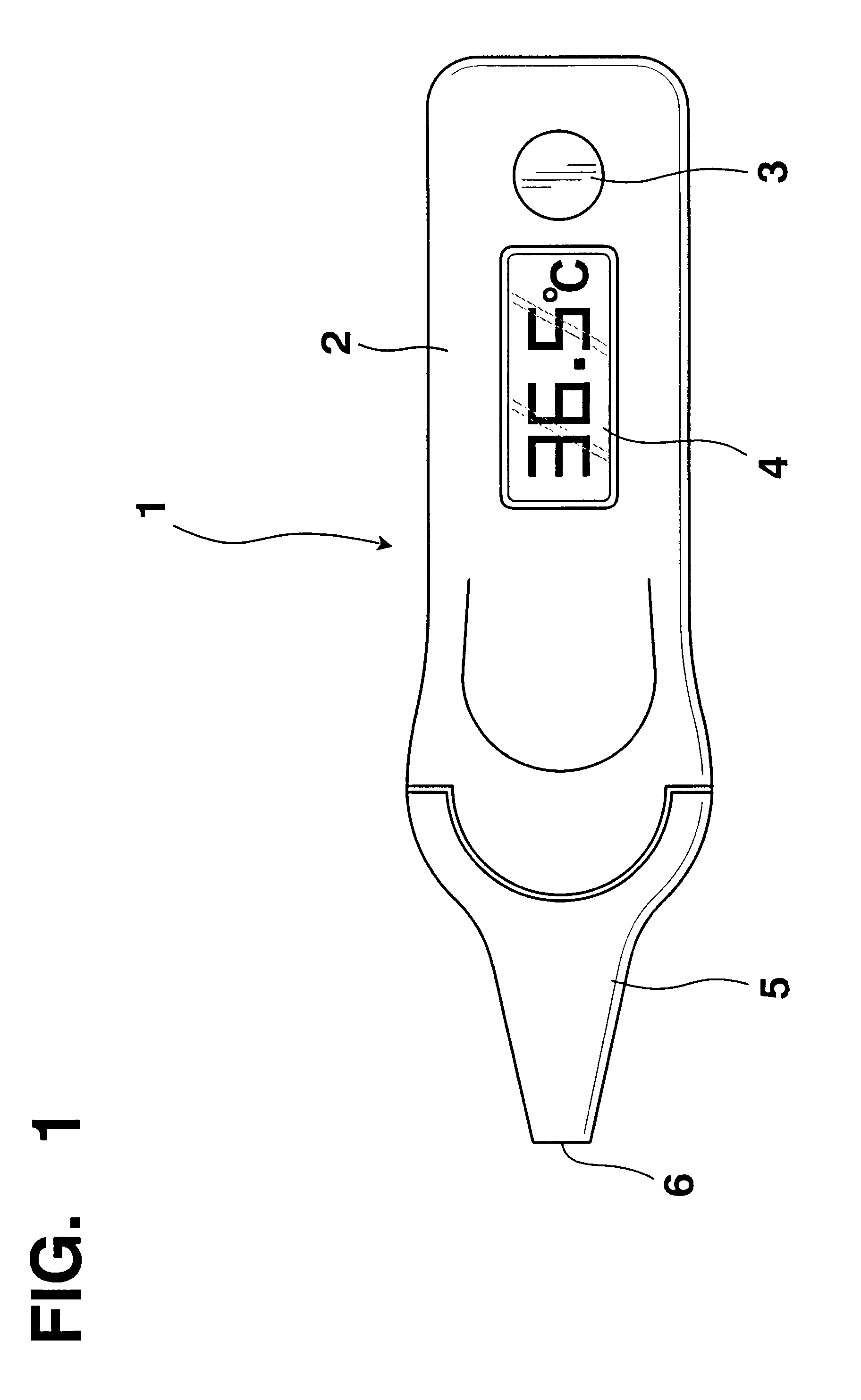
FIG. 1 is a schematic view of a radiation thermometer according to the present invention.

As shown in FIG. 1, a radiation thermometer 1 has a measuring switch 3 and a display 4 on case means 2. A probe portion 5 is provided at the front end of the case means 2.

The probe portion 5 has a conical trapezoidal shape with its diameter gradually increasing from the front end toward the rear end. The probe portion 5 is structured such that when the probe portion 5 is inserted into an external acoustic opening, the external acoustic opening is almost filled with a portion of the probe portion 5 thicker than the external acoustic opening. The shape of the probe portion is not necessarily limited to this so long as the probe portion substantially fills the external acoustic opening.

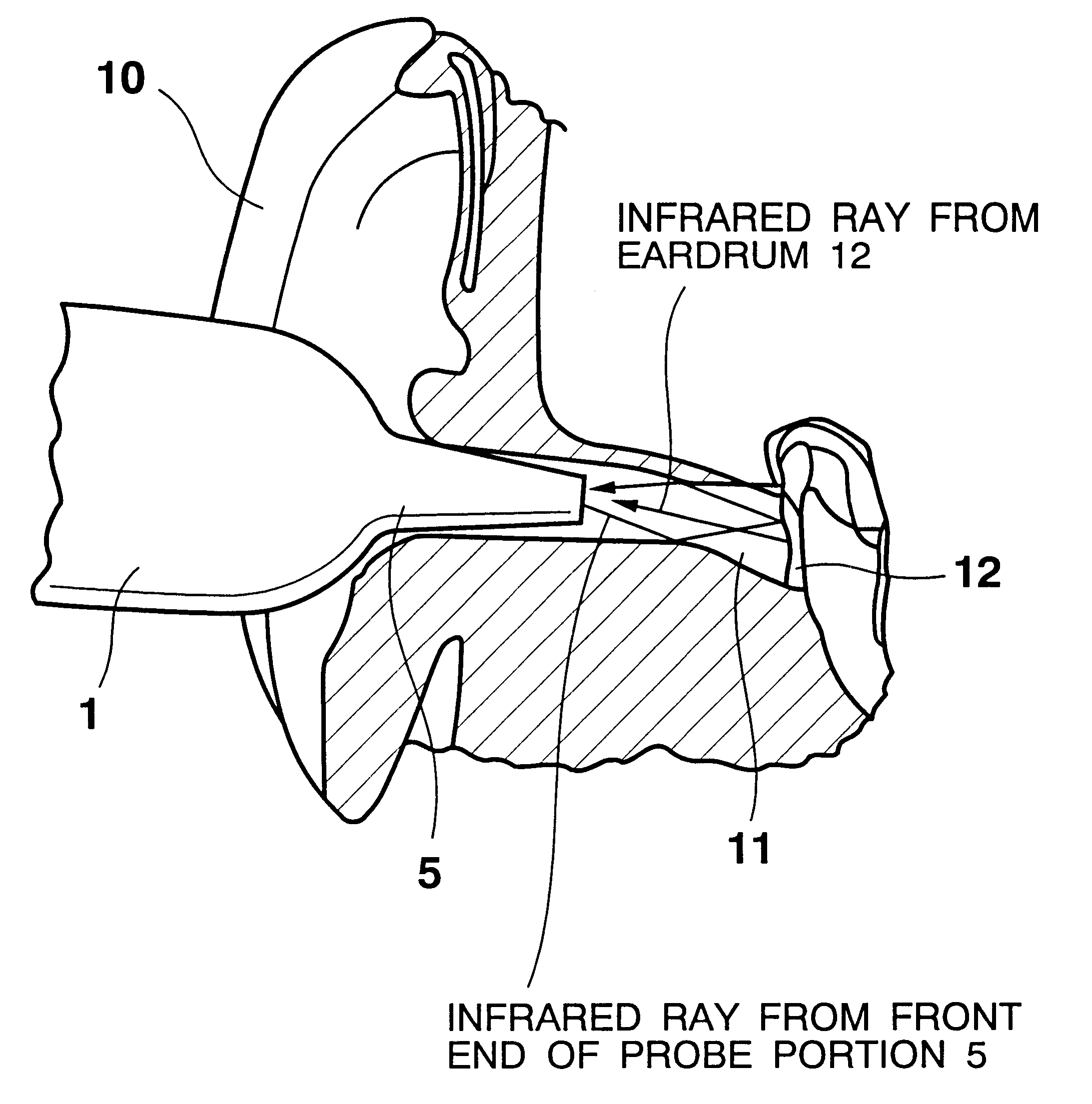
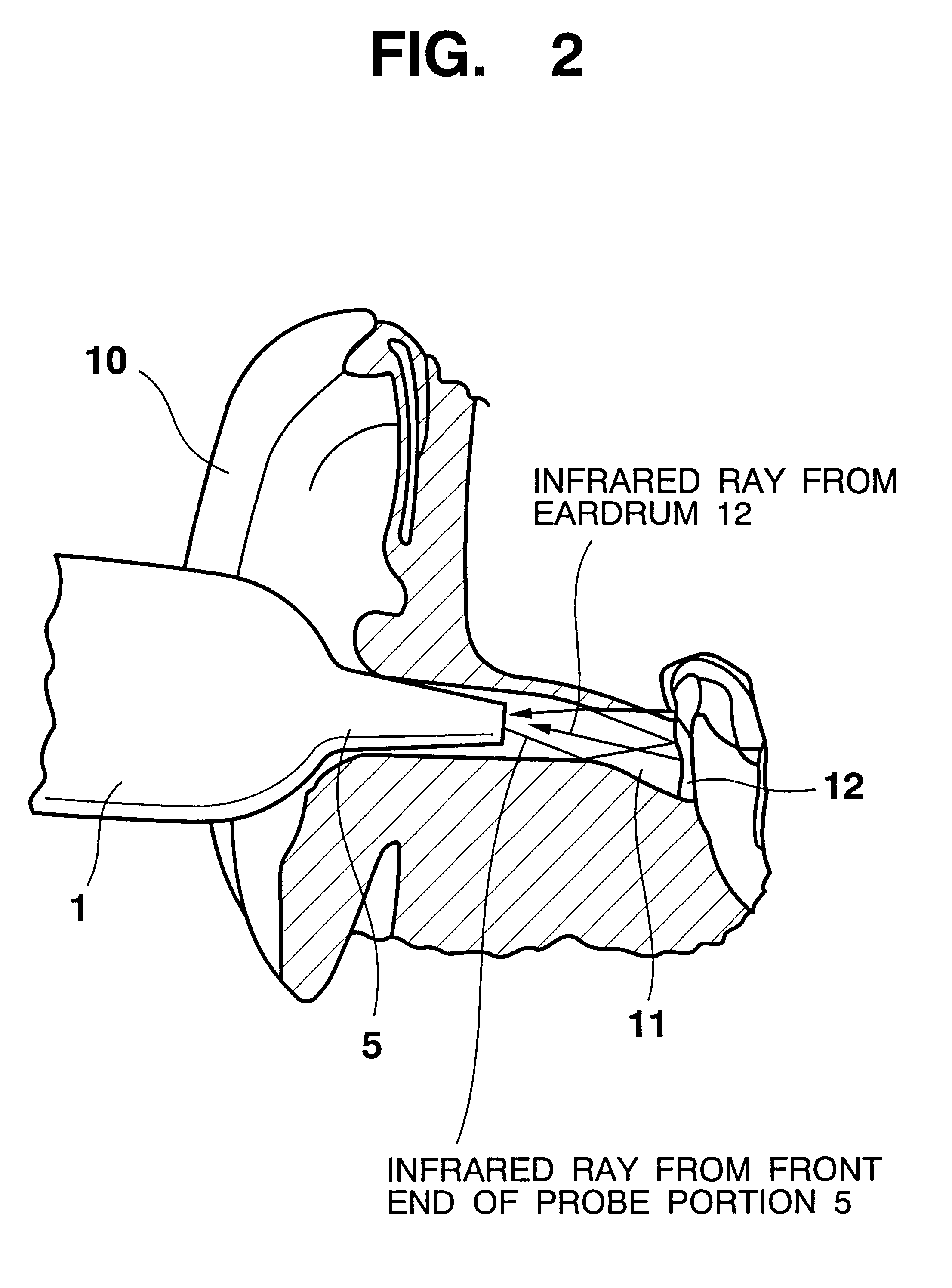
For measuring a body temperature, the measuring switch 3 is depressed, and then the front end of the probe portion 5 is inserted into an external acoustic opening 11. The radiation thermometer 1 starts the measuremen...

second embodiment

the present invention will be explained next.

FIG. 8 is a cross-sectional view of a probe portion 5 of a radiation thermometer according to a second embodiment of the present invention.

A difference from the embodiment shown in FIG. 3 is that there is no thermistor 21.

A difference between a temperature of an infrared ray sensor 18 and a temperature of the front end of a probe portion 5 is smaller than a difference between a temperature of an eardrum 12 or an external acoustic opening 11 as an object under measurement and a temperature of the front end of the probe portion 5. Therefore, in order to simplify the structure, the thermistor 21 shown in FIG. 3 can be substituted with the thermistor 20.

In this case, T.sub.0 can be set to T.sub.p in the expression 2. The operation to be carried out by the operational circuit 28a is given by expression 3.

T.sub.b =(T.sub.0.sup.4 +V.sub.b / Ke).sup.1 / 4 (3)

In the present embodiment, an output voltage of the thermistor 20 can be used as the tempera...

third embodiment

the present invention will be explained next.

In the third embodiment, it is an object to simplify the structure and to increase the processing speed by approximating the numerical expression given in the expression (3) in terms of a more simple expression.

When the function f (T)=T.sup.4 is depicted into a graph in respect to T as an absolute temperature, a curve as shown in FIG. 9 is obtained. In FIG. 9, a horizontal axis represents T and a vertical axis represents f (T).

In the curve shown in FIG. 9, when the radiation thermometer 1 is actually used at an environmental temperature (that is, when a range of the temperature T.sub.0 of the infrared ray sensor 18 is observed), a narrow range of about 288.degree. K (15.degree. C.) to 308.degree. K (35.degree. C.) will be noted, assuming that the radiation thermometer 1 is usually used indoors. Further, a temperature range of the eardrum 12 or the external acoustic opening 11 that is the object under measurement is about 308.degree. K (35...


PUM

PropertyMeasurementUnit
emissivityaaaaaaaaaa
thicknessaaaaaaaaaa
emissivityaaaaaaaaaa

Abstract

To provide a radiation thermometer capable of measuring a body temperature more accurately than it has been conventionally possible, by taking into account an infrared ray that is emitted from a front end of the probe portion and reflected from an eardrum or an external acoustic opening. The radiation thermometer has body temperature calculating means for calculating a body temperature according to a predetermined arithmetic expression based on an emissivity when the emissivity of the eardrum or the external acoustic opening is less than 1, an output of infrared-ray detecting means and an output of temperature-measuring means.

Description

1. Field of the InventionThe present invention relates to a radiation thermometer.2. Description of the Prior ArtFor the purpose of measuring a body temperature in a short period of time, a radiation thermometer which selects an eardrum as a measurement site and measures a temperature of the eardrum in a non-contact manner has been already proposed.An example is a radiation thermometer which is disclosed in Japanese Laid-open Patent Publication No. 28524 / 1990. This radiation thermometer allows a front end of a probe portion, which comprises a window member at a front end and an infrared ray sensor at a rear end, to be inserted into an external acoustic opening, so that an infrared ray from the eardrum is received by the infrared ray sensor through the window member, and the temperature of the eardrum, i.e. the body temperature, is measured based on the intensity of the received infrared ray.Since this type of radiation thermometer measures a body temperature based on the intensity o...

Claims


Application Information

Patent Timeline
Patent Type & Authority Patents(United States)
IPC IPC(8): G01K13/00A61B5/01G01J5/04
CPCG01J5/0003G01J5/0011G01J5/02G01J5/025G01J5/026G01J5/04G01J5/08G01J5/0818G01J5/0875G01J5/16G01J5/049G01J2005/068G01J2005/0048G01J5/064G01J5/80
Inventor EGAWA, SHUNJI
Owner CITIZEN WATCH CO LTD
Why Eureka
Try Eureka