Heat regulating unit

Inactive Publication Date: 2003-06-03
HAMPDEN CHRIS
View PDF7 Cites 16 Cited by
  • Summary
  • Abstract
  • Description
  • Claims
  • Application Information

AI Technical Summary

Problems solved by technology

However, such previous known heat exchangers are not particularly efficient and require use of an additional blower to cause air to pass through the heat exchanger.
Also, heating air recycle

Method used


Image

  • Heat regulating unit
  • Heat regulating unit
  • Heat regulating unit

Examples


Embodiment Construction

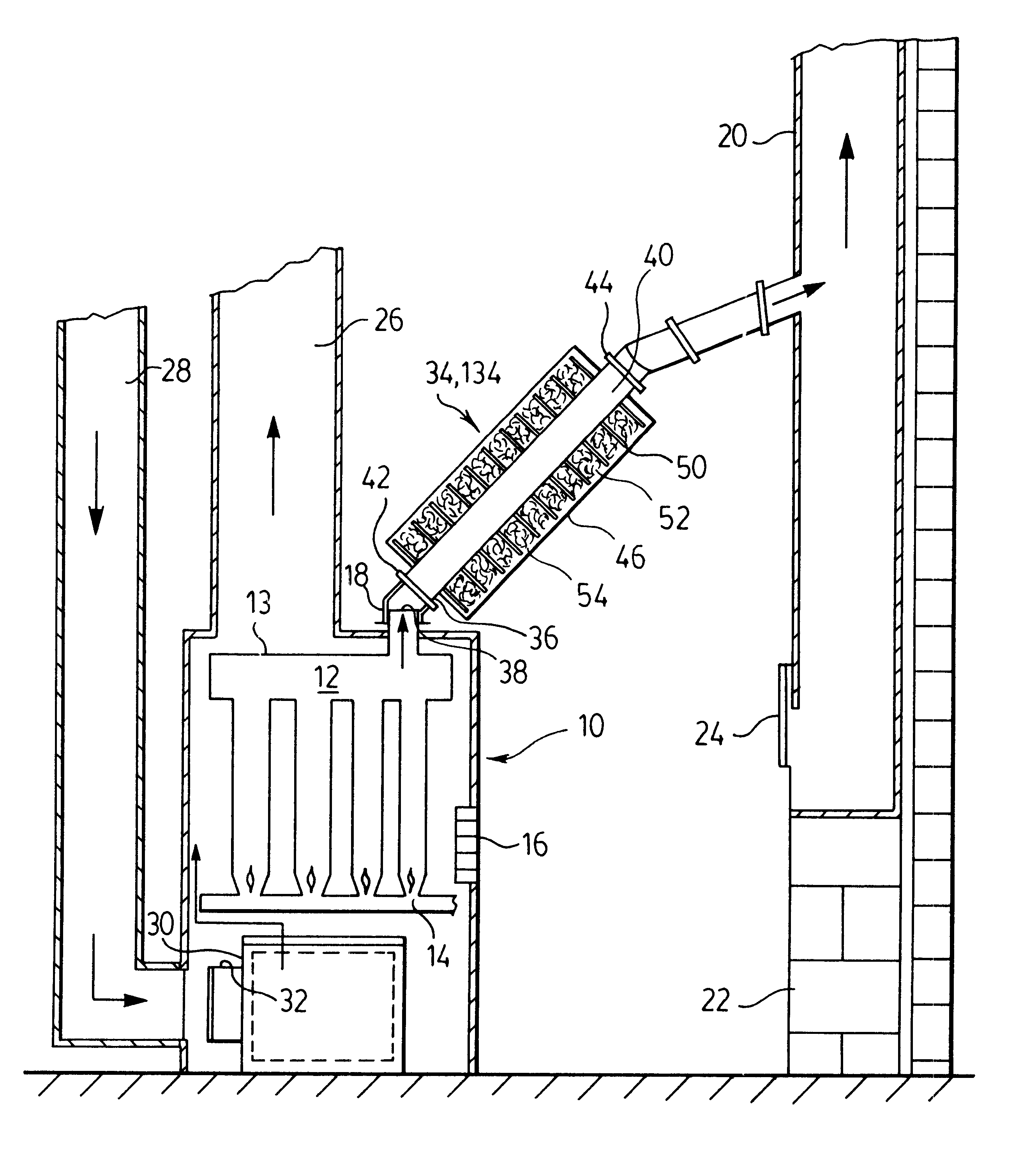
An installation of a heat regulating installation shown in FIGS. 1-3 was tested with a Findlay 140,000 BTU conventional gas-fired furnace. The outside temperature was -2.degree. C. and the wind speed was 15 to 20 km / h. A comparative test was conducted under the same conditions with the Findlay 140,000 BTU furnace without the heat recovery system.

FIG. 6 illustrates burner time and blower time on and off in 12-minute cycles for the Findlay furnace without the heat recovery system. The burner fired on for three minutes and was off for nine minutes, with the blower on for about five minutes of the cycle. FIG. 7 illustrates burner and blower time on and off for the 12-minute cycle for the Findlay furnace having the heat regulating unit installed. The burner fired for only two minutes and was off for 10 minutes, with the blower on for about four minutes of the cycle.

The heat regulating unit of the invention provides a number of important advantages. Apart from the initial cost of the unit...


PUM


Abstract

A forced air heating system has a heat regulating unit assembled therewith, the heating system comprising a furnace having fuel burner and a flue pipe for outlet gases. The heat regulating unit has a metal flue conduit with a flue gas inlet and a flue gas outlet connected to the flue pipe in proximity to the furnace to form a portion of the flue pipe. An elongated casing surrounds the flue conduit and defines with the flue an annulus in which a series of equispaced metal fins extend radially from the flue conduit to the casing to define chambers containing a heat-absorbing material such as metal wool. The heat regulating unit functions as a heat-sink to absorb heat from the hot fuel and a heat source gases for return to the furnace by conduction and convection.

Description

(i) Field of the InventionThis invention relates to heat regulating units for forced air heating systems.(ii) Description of the Related ArtIt is known to recover heat from the flue gases of a forced air heating system having a fuel burner by surrounding the flue pipe with a heat exchanger through which heated air is recycled to the heating system, the air being heated in the heat exchanger by heat recovered from the flue gases. However, such previous known heat exchangers are not particularly efficient and require use of an additional blower to cause air to pass through the heat exchanger.Also, heating air recycled to the heating system from a heat exchanger in contact with hot flue gases may receive toxic gases such as carbon monoxide if the heat exchanger should leak due, for example, to corrosion.It is therefore an object of the invention to provide an improved heat regulating unit which does not require use of an additional blower to cause air to pass through the heat exchanger...

Claims


Application Information

Patent Timeline
IPC IPC(8): F27D17/00F28D20/00F27D19/00
CPCF27D17/004F28D20/0056F27D19/00Y10S165/901Y02E60/142Y02E60/14Y02P80/15
Inventor HAMPDEN, CHRIS
Owner HAMPDEN CHRIS
Why Eureka
Try Eureka