Gas preheater and process for controlling distribution of preheated reactive gas in a CVI furnace for densification of porous annular substrates

a technology of preheated reactive gas and cvi furnace, which is applied in the direction of lighting and heating apparatus, furnaces, charge manipulation, etc., can solve the problems of not always as good as desired gas preheater efficiency, temperature gradient not only in the vertical direction, and reduce the loading capacity of substrates, etc., to achieve uniform densification, reduce the effect of temperature gradient, and improve the efficiency of gas preheating

Inactive Publication Date: 2003-06-03
SAFRAN LANDING SYSTEMS
View PDF1 Cites 57 Cited by
  • Summary
  • Abstract
  • Description
  • Claims
  • Application Information

AI Technical Summary

Benefits of technology

resting upon the susceptor bottom wall and being thus surrounded by the susceptor side wall, it enables an efficient heating of the preheating zone to be reached,
it encloses the preheating zone and contributes to the sealing thereof, avoiding a large fraction of the reactive gas admitted to reach the reaction chamber without having fully passed through the gas preheater, and
it supports the load of substrates through the gas distribution plate and load supporting plate and transfers the weight to the susceptor bottom wall without the need for a separate supporting structure for the load supporting plate.
The above contributes to the efficiency of the gas preheating and compactness of the structure located at the bottom of the furnace.
The provision of flow adjusting nozzles which may be inserted in the passages of the gas distribution plate, makes it possible to feed stacks of substrates with a larger flow of reactive gas compared to other stacks of substrates. It is thus possible to compensate for a gradient of temperature between different stacks of substrates in order to achieve a substantially uniform densification. Indeed, the deposition rate of the matrix material varies as a function of the temperature and of the flow of reactive gas.
According to a particular aspect of the invention, the heat exchange assembly of the gas preheater comprises a plurality of spaced apart plates surrounded by the sleeve and extending substantially horizontally between the susceptor bottom wall and the gas distribution plate, the plates of the heat exchange assembly being made of a heat conductive foil material. The use of foil material such as graphite foil material or of C / C composite material makes it possible to reduce the thickness of the plates, hence the bulk of the gas preheater. The plates, which may be of a substantially circular form, are then preferably spaced apart by means of radially extending spacers interposed therebetween.

Problems solved by technology

The applicants have found that the efficiency of the gas preheater is not always as good as desired.
However, for a given volume of the furnace, that would reduce the loading capacity for the substrates.
Another problem resides in the fact that a temperature gradient is observed not only in the vertical direction, along the stacks of substrates, but also in the horizontal direction, between different stacks.
In particular, it has been noted that stacks located in a central part of the reaction chamber may not benefit from the heat radiated by the susceptor in the same way as stacks located closer to the internal side wall of the susceptor.

Method used


Image

  • Gas preheater and process for controlling distribution of preheated reactive gas in a CVI furnace for densification of porous annular substrates
  • Gas preheater and process for controlling distribution of preheated reactive gas in a CVI furnace for densification of porous annular substrates
  • Gas preheater and process for controlling distribution of preheated reactive gas in a CVI furnace for densification of porous annular substrates

Examples


Embodiment Construction

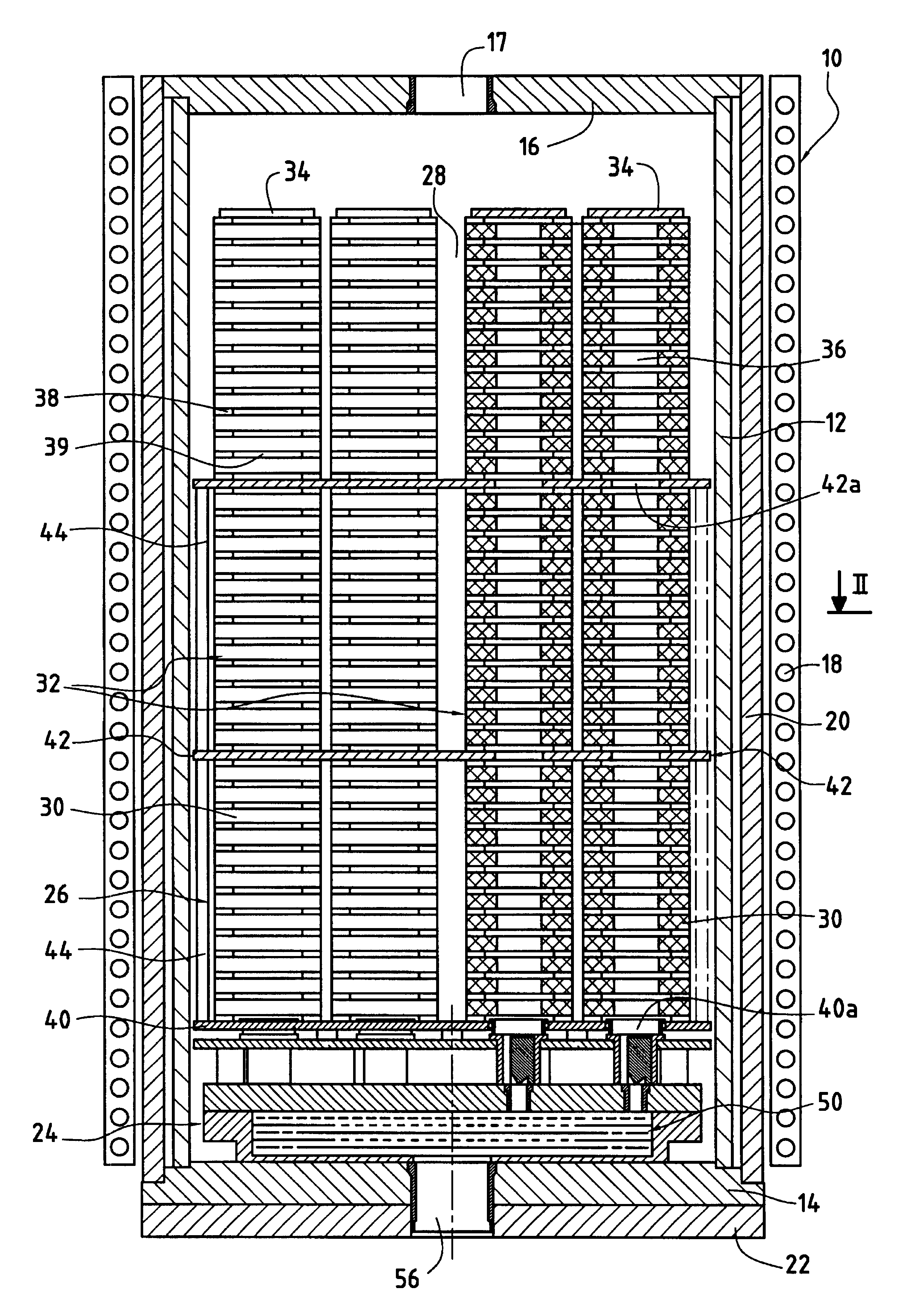
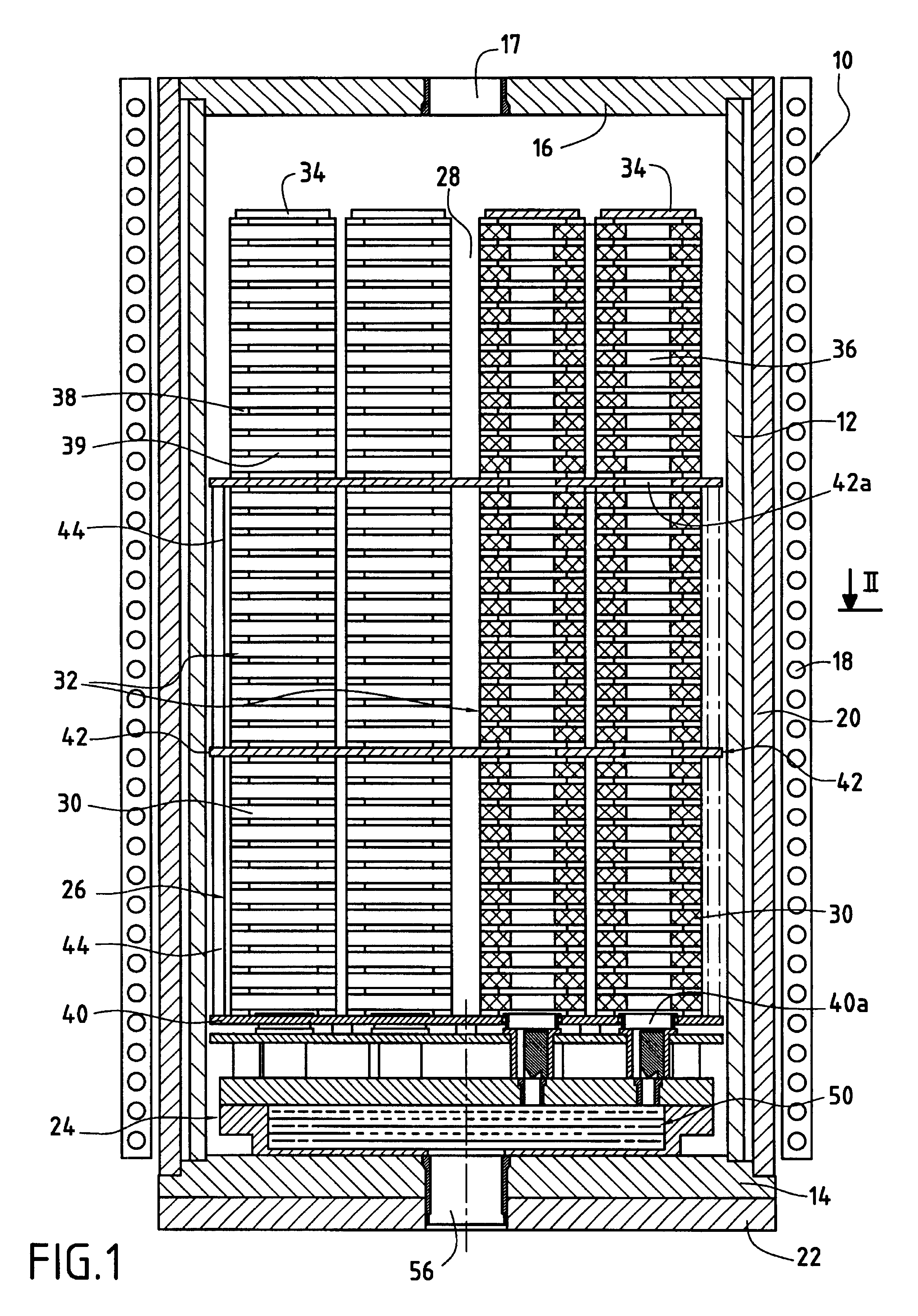
FIGS. 1 and 2 show a furnace 10 having a cylindrical side wall 12 formed by a susceptor, with a susceptor bottom wall 14 and a susceptor top wall 16. The susceptor 12 constitutes a secondary transformer circuit which is inductively coupled with a primary transformer circuit in the form of at least one induction coil 18. Insulation 20 is interposed between the induction coil 18 and the susceptor 12 and further insulation 22 is provided under the susceptor bottom wall 14. The furnace 10 is heated by feeding electrical current to the induction coil 18. As a variant, heating of the susceptor can be carried out by means of electrical resistors thermally coupled thereto.

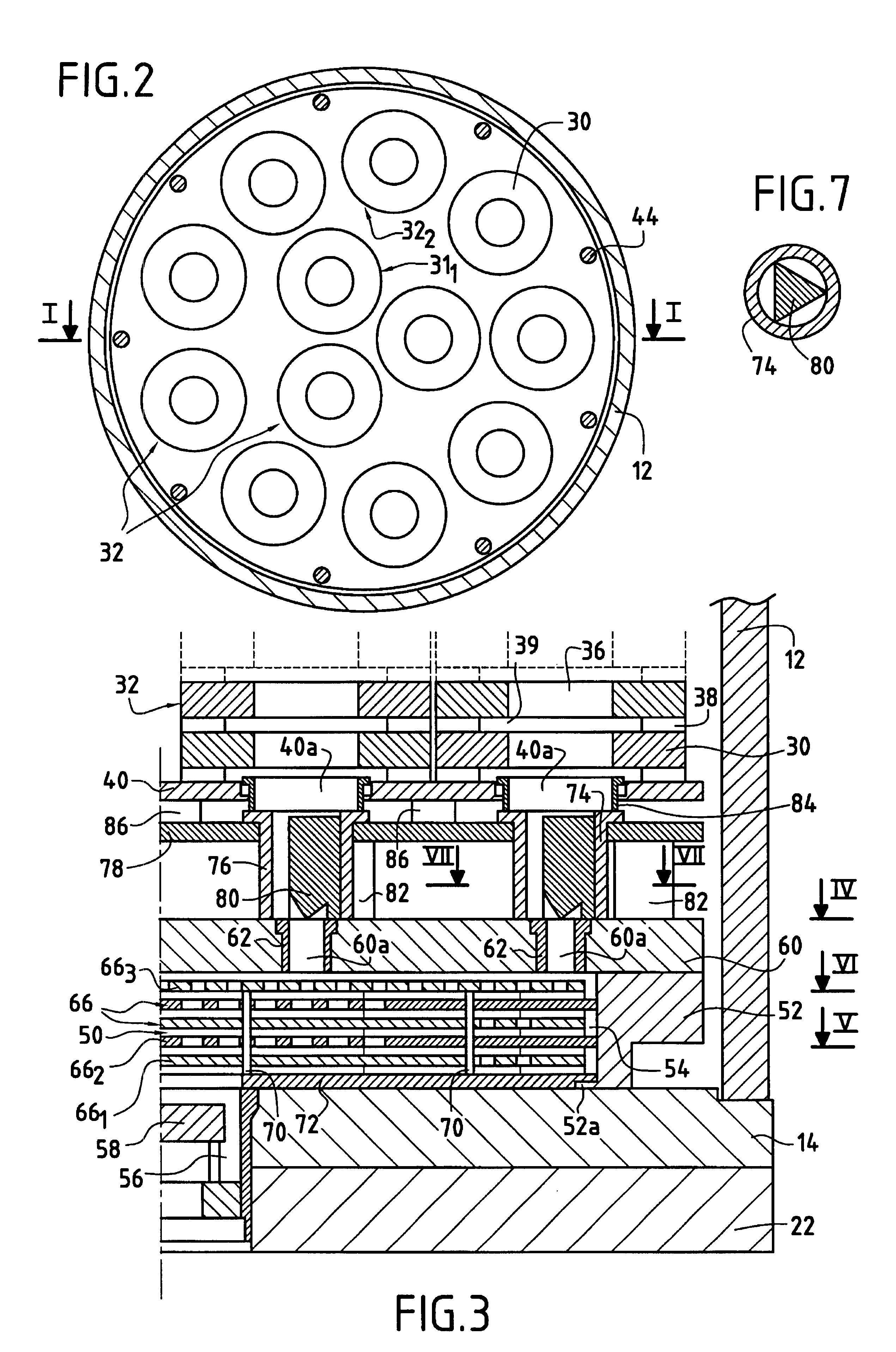
The internal volume of the furnace 10 comprises a gas preheating zone 24 located at the bottom of the furnace and a reaction chamber or loading zone 26 where porous annular substrates 30 to be densified are loaded, the reaction chamber 26 being located above the preheating zone 24.

The substrates 30 to be densified may cons...


PUM

PropertyMeasurementUnit
temperatureaaaaaaaaaa
heat conductiveaaaaaaaaaa
internal volumesaaaaaaaaaa

Abstract

A gas preheater for a CVI furnace designed for the densification of annular porous substrates arranged in a plurality of vertical annular stacks of substrates, comprising: a sleeve made of heat conductive material resting upon the bottom wall of a susceptor and delimiting a gas preheating chamber, with a gas inlet opening in the gas preheating chamber; a heat exchange assembly located in the gas preheating chamber; a gas distribution plate resting upon the sleeve, covering the gas preheating chamber and provided with a plurality of passages for preheated gas; a load supporting plate for supporting stacks of annular substrates and provided with a plurality of passages in communication with respective passages of the gas distribution plate and registration with internal volumes of respective stacks of annular substrates; and nozzles inserted in passages communicating the gas preheating zone with the internal volumes of respective stacks of annular substrates for adjusting the flows of preheated gas respectively admitted in said internal volumes.

Description

The invention relates to densification of porous annular substrates by chemical vapor infiltration (CVI).A particular field of application of the invention is the making of annular parts in a thermostructural composite material, such as carbon / carbon (C / C) composite brake discs for airplanes or land vehicles.Thermostructural composite materials are remarkable because they possess mechanical properties that enable them to be used for making structural parts and have the ability to conserve these properties at high temperatures. Typical examples of thermostructural composite materials are C / C composite materials having a reinforcing fibrous texture of carbon fibers densified by a pyrolytic carbon matrix, and ceramic matrix composites (CMCs) having a reinforcing texture of refractory fibers (carbon or ceramic) densified by a ceramic matrix.In a CVI process, substrates to be densified are placed in a reaction chamber of a furnace in which they are heated. A reactive gas containing one o...

Claims


Application Information

Patent Timeline
Patent Type & Authority Patents(United States)
IPC IPC(8): C23C16/04C23C16/26C23C16/452
CPCC23C16/26C23C16/045C23C16/04
Inventor SION, ERICBAUDRY, YVAN
Owner SAFRAN LANDING SYSTEMS
Why Eureka
Try Eureka