Transducer for microfluid handling system

Inactive Publication Date: 2003-06-10
NANONORD
View PDF18 Cites 142 Cited by
  • Summary
  • Abstract
  • Description
  • Claims
  • Application Information

AI Technical Summary

Benefits of technology

It is an advantage of the present invention that piezoresistors are integrated and used to measure the deflections of the flexible members.
that piezoresistors are integrated and used to measure the deflections of the flexible members.
It is a still further advantage of the present invention that a plurality flexible members can be integrated closely together in a micro-system, so that one flexible member can serve as a reference to another, or that nearby flexible members can be immersed in different laminated streams in a fluid flow, so that one fluid can serve as a reference to another.
It is a still further advantage of the present invention that it provides a sensor where the liquid volume is minimised in order to reduce the use of chemicals and in order to obtain a system which is easy to stabilise thermally.
The above object, advantages and features, together with numerous other advantages and features will be evident from the detailed description below of preferred embodiments of the present invention.
FIG. 1: Schematic cross-sectional view of a micro-channel with integrated micro-cantilever.

Problems solved by technology

Often the stress formation will result in a deflection of the micro-cantilever.
If the magnetic beads bind to the surface, the application of a large magnetic field will cause a bending of the micro-cantilever.
It is a disadvantage of the above-mentioned systems that micro-cantilever based experiments are carried out in large liquid containers.
Such large liquid container systems are very difficult to stabilise thermally.
Furthermore, in such large container systems the required volume of chemicals is unnecessary high.
It is a further disadvantage of most of the above-mentioned systems that the micro-cantilever deflection is detected optically.
This disadvantage is due to the fact that it may be difficult to obtain optical access to a specific micro-cantilever--especially in the case where a plurality of micro-cantilevers are closely spaced and in the case where the liquid is not transparent.
As a result, the flexible sensor will be stressed due to the bimetallic effect.
However, for an array of microscopic flexible structures, this type of read-out becomes very complicated and operation in liquid is even more problematic.
At present, very few experiments have been carried out on biological systems, which normally implies a liquid environment, and microscopic flexible structures with integrated read-out have rarely been applied.
Such micro-cantilevers are not necessarily optimally designed for biochemical sensing.

Method used


Image

  • Transducer for microfluid handling system
  • Transducer for microfluid handling system
  • Transducer for microfluid handling system

Examples


example 2

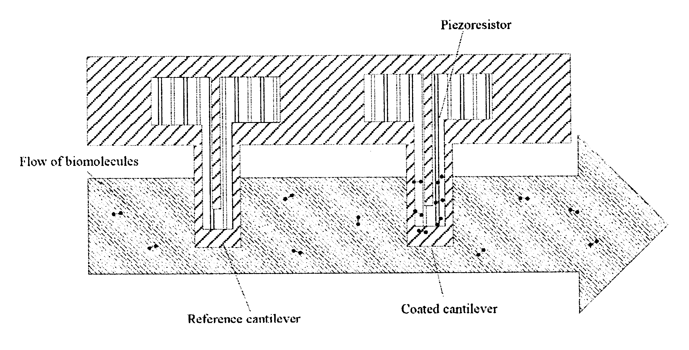
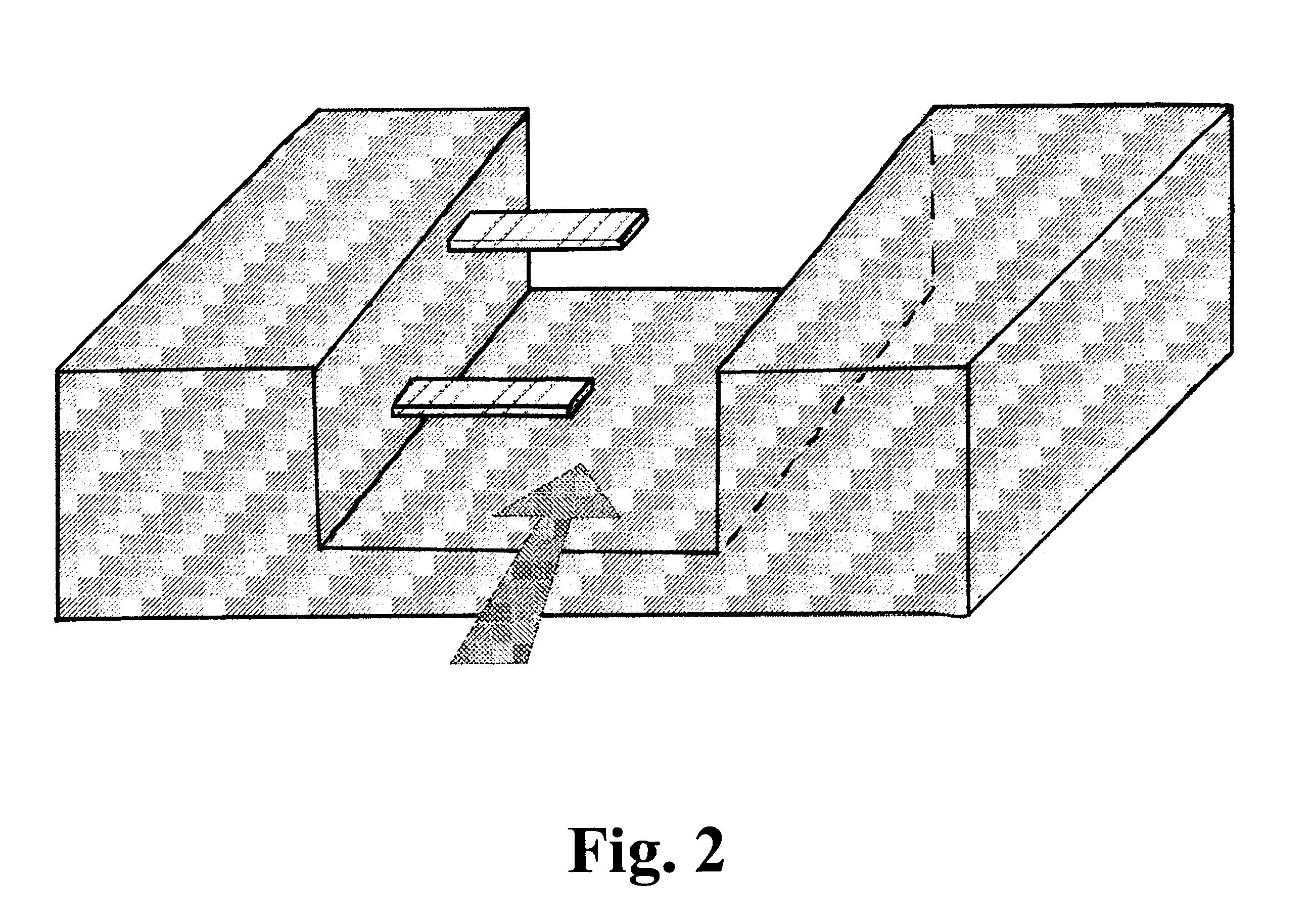
Micro-membrane-based Sensor

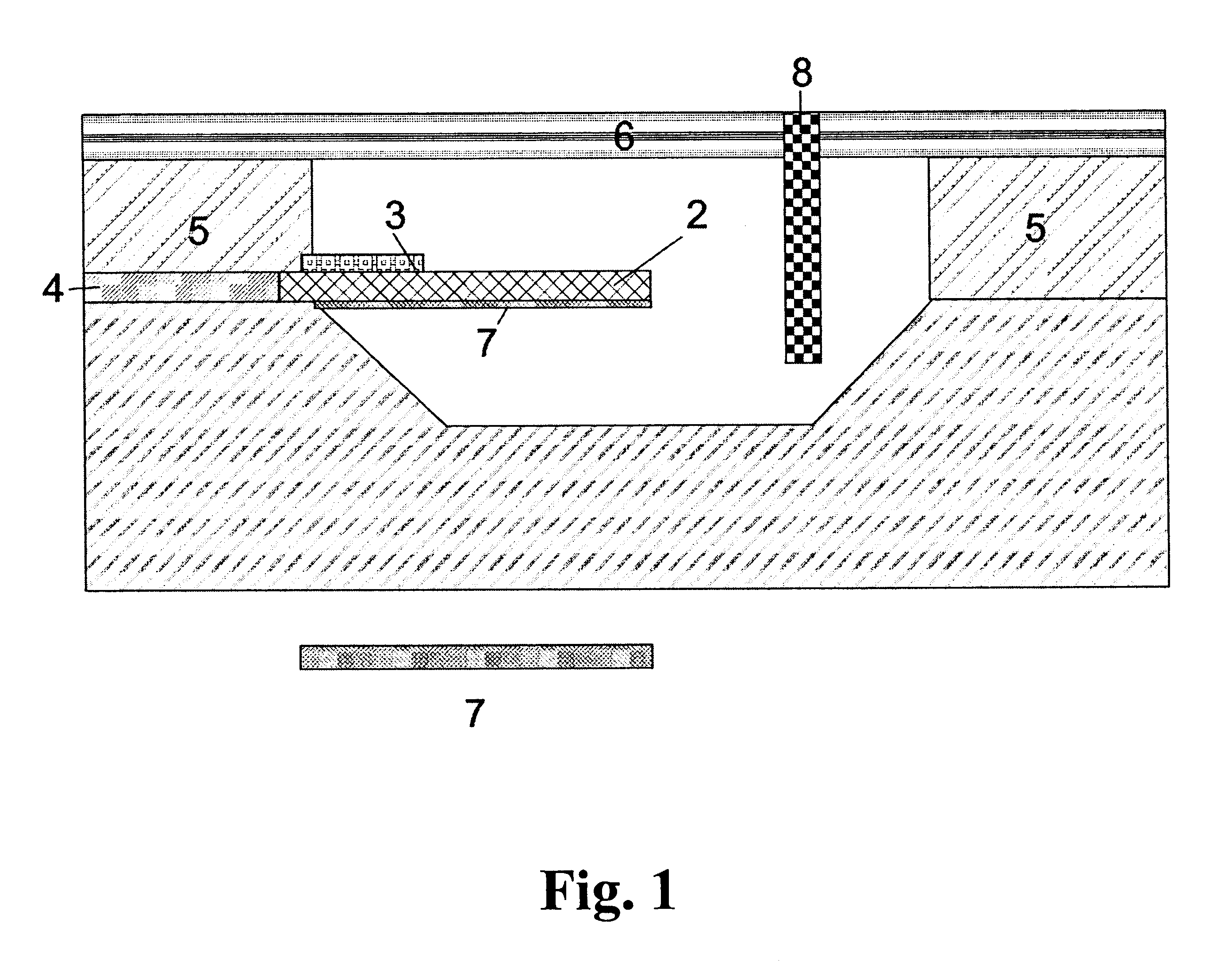
For the fabrication of a micro-membrane-based sensor in a channel, the fabrication is also performed by micromaching. In contrast to the micro-cantilever or micro-bridge-based sensor, the micro-membrane is normally placed in the bottom of the channel. This design makes it possible to contact the resistors from the backside. Nevertheless, in following example the resistors will be contacted from the same side as the channel.

The first steps ( FIG. 5.a.-5.f.) in the fabrication sequence is basically the same as descriebed for the micro-cantilever or micro-bridge based sensor.

After the resistors have been defined by RIE the resistors are encapsulated in a 50-200 nm thick thermal oxide. Hereafter, a 20-100 nm thick LPCVD nitride is deposited to be used as an etch mask, but also as a diffusion barrier (FIG. 10.a.).

For the fabrication of contact holes through the nitride / oxide layer, a thin resist is spun on top of the wafer. The contact-hole mask is transferred ...


PUM


Abstract

The present invention relates to integrated micro-cantilevers, micro-bridges or micro-membranes in micro-liquid handling systems. Such micro-liquid handling systems provide novel detection mechanisms for monitoring the physical, chemical and biological properties of fluids in such systems. The present invention further relates to micro-cantilever, micro-bridge or micro-membrane type sensors having integrated readout. Such constructions allow laminated flows of different liquids to flow in a channel without mixing, which opens up for new type of experiments and which reduces noise related to the liquid movement. The present invention even further relates to sensors having adjacent or very closely spaced micro-cantilevers, micro-bridges or micro-membranes which can be exposed to different chemical environments at the same time.

Description

The present invention relates to a sensor using microscopic flexible mechanical structures such as micro-cantilevers, micro-bridges or micro-membranes integrated into microscopic chambers. In particular, the present invention relates to a sensor for measuring biochemical properties of fluids in such chambers.TECHNICAL BACKGROUNDThe measurement of the properties of fluids flowing in microscopic channels is of importance in the field of micro liquid handling systems, which includes systems for measuring: 1) physical properties such as flow rates viscosity and local temperature 2) chemical properties such as pH and chemical composition 3) biological properties such as identification of organic constituents in fluids, including DNA fragments, proteins, and complete biological cellsMicroliquid handling systems typically consist of narrow channels of order 100 microns wide and 100 microns deep engraved or embossed into the surface of a thin wafer of a material such as silicon, glass or pl...

Claims


Application Information

Patent Timeline
IPC IPC(8): G01N11/00G01N11/10G01N27/00G01N11/16G01N9/00G01N35/00
CPCG01N9/002G01N11/00G01N11/16G01N29/022G01N29/036G01N29/222G01N29/30G01N2291/0427G01N2035/00237G01N2291/0215G01N2291/0224G01N2291/0255G01N2291/0256G01N2291/02818
Inventor DE CHARMOY GREY, HASIN FRANCOISJENSENIUS, TOVE MARIA HENRIETTETHAYSEN, JACOBBOISEN, ANJA
Owner NANONORD
Why Eureka
Try Eureka