Integrated precast footings

a precast footing and integrated technology, applied in the direction of foundation engineering, walls, forms/shuttering/falseworks, etc., can solve the problems of pre-existing drainage characteristics, pre-existing drainage characteristics of specific and surrounding soils, damage to the environment and water quality, so as to achieve smooth interface, improve the degree of quality control, and improve the effect of cap fi

Inactive Publication Date: 2003-06-17
GAGLIANO RICHARD J
View PDF41 Cites 44 Cited by
  • Summary
  • Abstract
  • Description
  • Claims
  • Application Information

AI Technical Summary

Benefits of technology

Since the component halves 1i and 1ii containing the sleeves have been pre-cast, a greater degree of quality control is provided than a site pour would allow, creating a smoother interface of the upper end of the sleeve and the concrete facet it is exposed on. This further allows for a better cap fit, and a more reliable, visually appealing finish.
The sleeves 3 are sized according to the diameter of the driven piles 2, allowing a sliding interface with minimal play. They are constructed of a substantially rigid thermoplastic material. Galvanized steel tubes, aluminum, and other alloys or composites may be substituted. In fact, an alternate arrangement is possible where the sleeve itself is removed during the pre-casting process, leaving cavities in the cured cementious material alone through which the piles may be driven. The piles are galvanized steel, but may be stainless steel, other suitable alloys, ceramics or composite materials of appropriate structural character. Finally, the completed assembly is shown resting on a pea gravel bed 14. For some applications, the addition of this material allows for the free flow of site drainage in any direction underneath the foundation system. In some regions, it will also act as a compressible component, allowing frost or clay heaving soils to push upward without transferring a destructive uplifting force on the system. This and other suitable materials, such as common compressible cardboard may be used to provide this function.

Problems solved by technology

"Improving" a site with the use of large machinery, extensive excavation and fill techniques, and the altering of drainage patterns and water tables damages the biological make up, structural integrity, and pre-existing drainage characteristics of the specific and surrounding soils.
This in turn can have damaging effects "downstream," where the accumulation of unwanted eroded material in streambeds can alter plant and animal habitat.
Man-made structures designed to replace the storage and filtering function of previously undisturbed soils by capturing unwanted drain waters and releasing them slowly back to the stream systems, can starve the watershed of its historic flow patterns, again causing damage to the environment and water quality.

Method used


Image

  • Integrated precast footings
  • Integrated precast footings
  • Integrated precast footings

Examples


Embodiment Construction

An example site has wooded vegetation. This vegetation can be cleared with small tracked equipment and dressed or smoothed, generally within the footprint area of the home and driveway only. It can be hydroseeded immediately and even have the topsoil layer placed beforehand. Smoothing means taking care that there are no low spots within the crawl space that would collect water. The site should be smoothed as close to the contours of the natural grade as possible with this one exception.

The next step is to mark out the foundation and lay 2 / 3" of pea gravel (rounded not crushed) along the outline of the house. In this example, the house has a wood framed floor over a crawl space, with an attached concrete slab floor garage. If the site is considerably sloped, batter boards should be erected to mark out a level and square reference. Rake the gravel smooth, to about 10" wide.

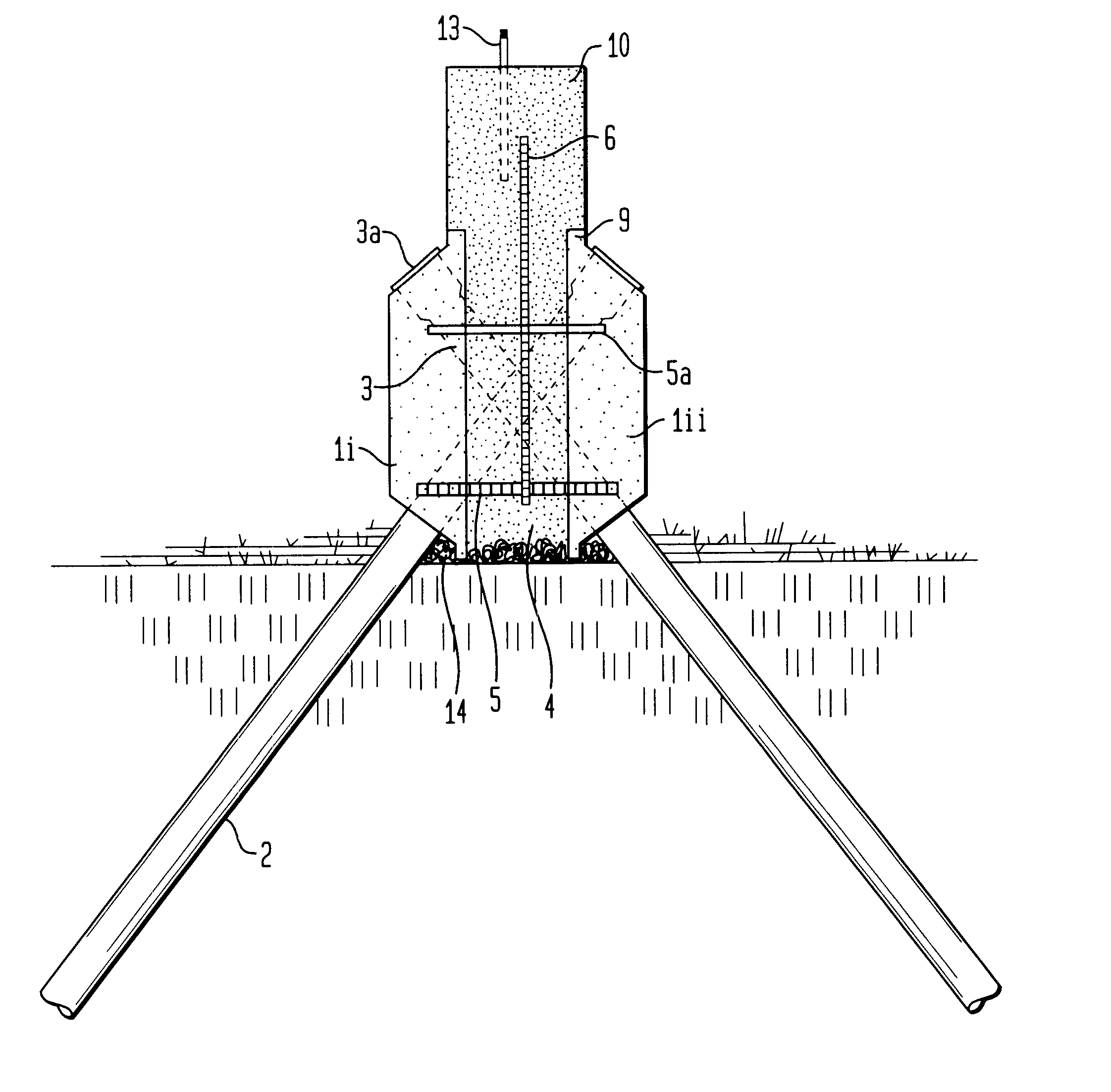
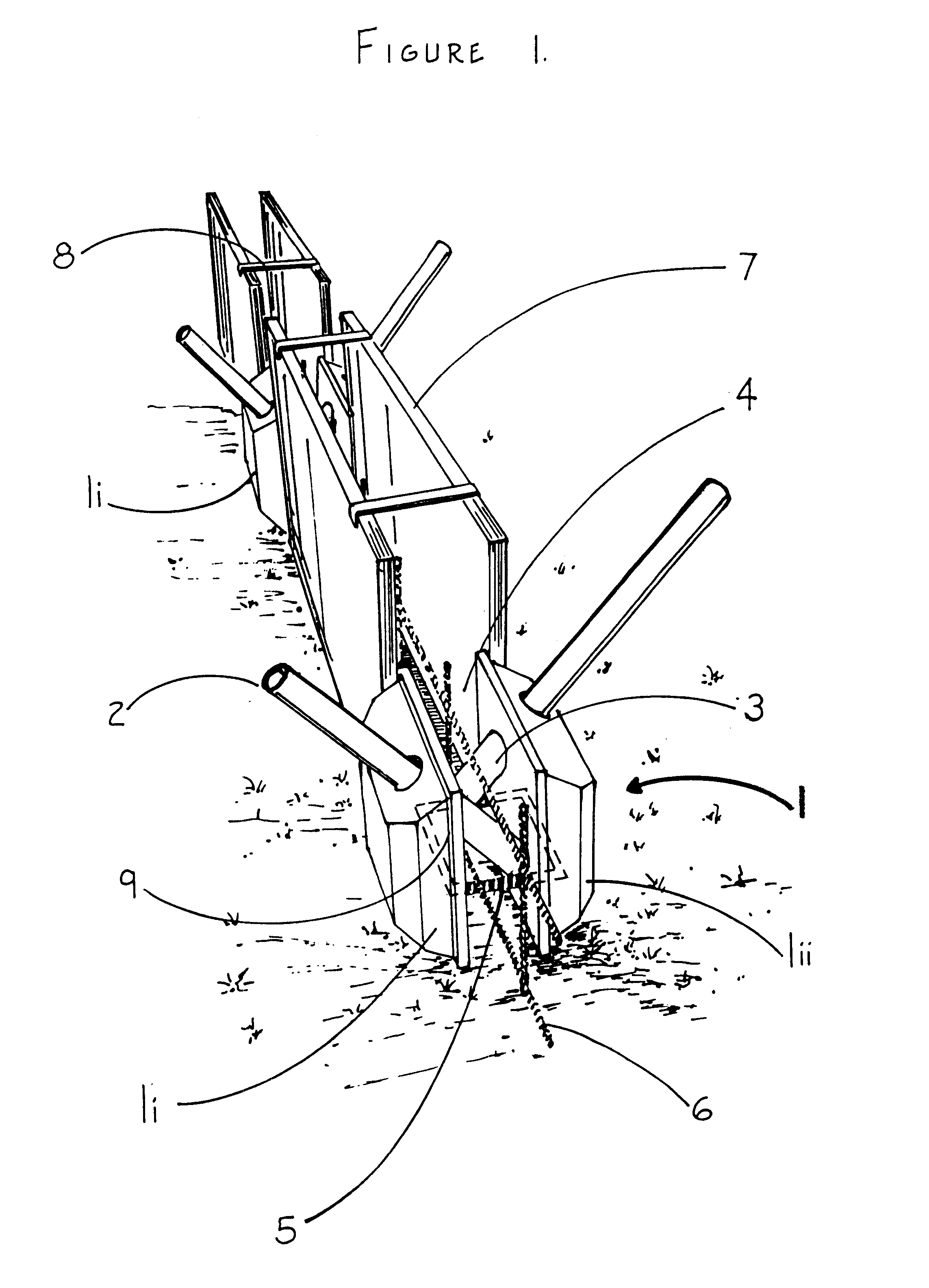
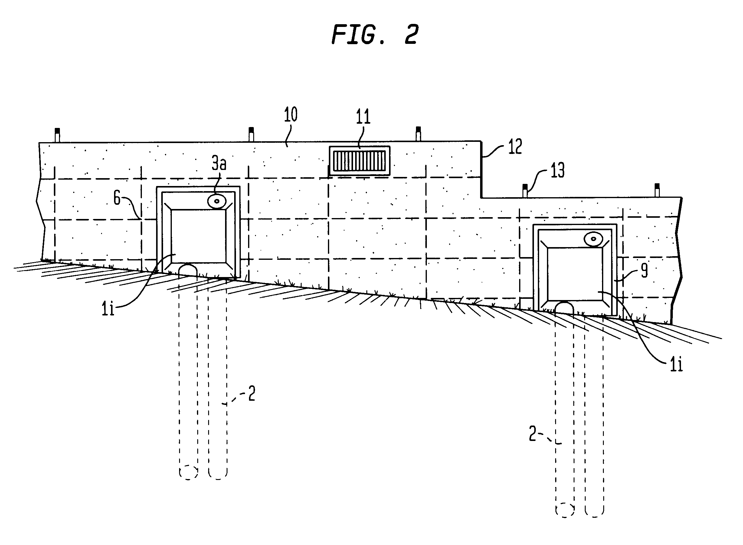
According to a pre-determined plan, the Integrated Pre-cast Footings (IPFs) should be placed at their required sp...


PUM


Abstract

A low impact foundation system requiring little or no excavation, and allowing for the preservation of the soil and drainage characteristics of the site upon which it is erected. The system utilizes small obliquely driven piles in combination with a pre-cast component designed to engage a standard foundation wall.

Description

The present invention generally relates to apparatus and methods for the support of surface structures. More specifically, the present invention provides improved pre-cast footing components configured for integration with the wall element of traditional foundations to create minimally intrusive foundation systems.The construction of surface structures invariably involves the preliminary task of building a foundation to support the structure. Most foundations prepared in current practice are comprised of a load bearing base known as a footing which is site poured with a cementious material into an excavation substantially below grade. The excavation provides for the footing to be founded on competent bearing soils beneath regional frost lines. Once cured, forming boards and a grid of internal reinforcing are constructed on top of the footing, allowing for the subsequent pouring of a cementious material to form a wall rising out of the excavation to a desired height above grade.The i...

Claims


Application Information

Patent Timeline
Patent Type & Authority Patents(United States)
IPC IPC(8): E02D27/32E04G13/00E04G17/14E02D27/01E02D27/50
CPCE02D27/01E04G17/14E04G13/00E02D27/50E02D27/013E02D27/016
Inventor GAGLIANO, RICHARD J.
Owner GAGLIANO RICHARD J
Why Eureka
Try Eureka