Multiple material golf club head

a golf club head and multi-material technology, applied in the field of golf club heads, can solve the problems of increased energy transfer problems, increased deformation of golf balls, and energy loss

Inactive Publication Date: 2003-06-24
TOPGOLF CALLAWAY BRANDS CORP
View PDF54 Cites 338 Cited by
  • Summary
  • Abstract
  • Description
  • Claims
  • Application Information

AI Technical Summary

Benefits of technology

The present invention has the face component 60 engage the crown 62 along a substantially horizontal plane. The crown 62 has a crown undercut portion 62a, which is placed under the return portion 74. Such an engagement enhances the flexibility of the striking plate portion 72 allowing for a greater coefficient of restitution. The crown 62 and the upper lateral section 76 are attached to each other as further explained below.
FIG. 12 illustrates a preferred embodiment of the face component of the golf club head of the present invention. FIG. 12 illustrates the variation in the thickness of the striking plate portion 72. The striking plate portion 72 is preferably partitioned into elliptical regions, each having a different thickness. In a preferred embodiment in which the face component 60 is composed of a titanium or titanium alloy material, a central elliptical region 102 preferably has the greatest thickness that ranges from 0.120 inch to 0.090 inch, preferably from 0.115 inch to 0.100 inch, and is most preferably 0.105 inch. The central elliptical region 102 preferably has a uniform thickness. A first concentric region 104 preferably has the next greatest thickness that ranges from 0.110 inch to 0.076 inch, preferably from 0.100 inch to 0.086 inch, and is most preferably 0.088 inch. The first concentric region preferably has a thickness that transitions from the first concentric region 102 thickness to the periphery region 110 thickness. A periphery region 110 preferably has the next greatest thickness that ranges from 0.082 inch to 0.062 inch, and is most preferably 0.072 inch. The variation in the thickness of the striking plate portion 72 allows for the greatest thickness to be localized in the center 111 of the striking plate portion 72 thereby maintaining the flexibility of the striking plate portion 72 which corresponds to less energy loss to a golf ball and a greater coefficient of restitution without reducing the durability of the striking plate portion 72.
FIG. 12A illustrates an alternative embodiment for the face component 60. In this embodiment, the striking plate portion 72 has an central elliptical region 102 which preferably has the greatest thickness that ranges from 0.120 inch to 0.090 inch, preferably from 0.115 inch to 0.100 inch, and is most preferably 0.105 inch. The central elliptical region 102 preferably has a uniform thickness. A first concentric region 104 preferably has the next greatest thickness that ranges from 0.110 inch to 0.090 inch, preferably from 0.104 inch to 0.094 inch, and is most preferably 0.098 inch. A second concentric region 106 preferably has the next greatest thickness that ranges from 0.100 inch to 0.080 inch, preferably from 0.095 inch to 0.085 inch, and is most preferably 0.088 inch. A third concentric region 108 preferably has the next greatest thickness that ranges from 0.090 inch to 0.070 inch, preferably from 0.083 inch to 0.073 inch, and is most preferably 0.080 inch. The concentric regions preferably each have a thickness that transitions from one adjacent region to another. A periphery region 110 preferably has the next greatest thickness that ranges from 0.072 inch to 0.061 inch. The periphery region includes toe periphery region 110a and heel periphery region 110b. The variation in the thickness of the striking plate portion 72 allows for the greatest thickness to be distributed in the center 111 of the striking plate portion 72 thereby enhancing the flexibility of the striking plate portion 72 which corresponds to less energy loss to a golf ball and a greater coefficient of restitution.

Problems solved by technology

Most of the energy is transferred from the head to the golf ball, however, some energy is lost as a result of the collision.
However, this leads to greater deformations in the golf ball, and thus increases in the energy transfer problem.
Although the prior art has disclosed many variations of multiple material club heads, the prior art has failed to provide a multiple material club head with a high coefficient of restitution and greater forgiveness for the typical golfer.

Method used


Image

  • Multiple material golf club head
  • Multiple material golf club head
  • Multiple material golf club head

Examples


Embodiment Construction

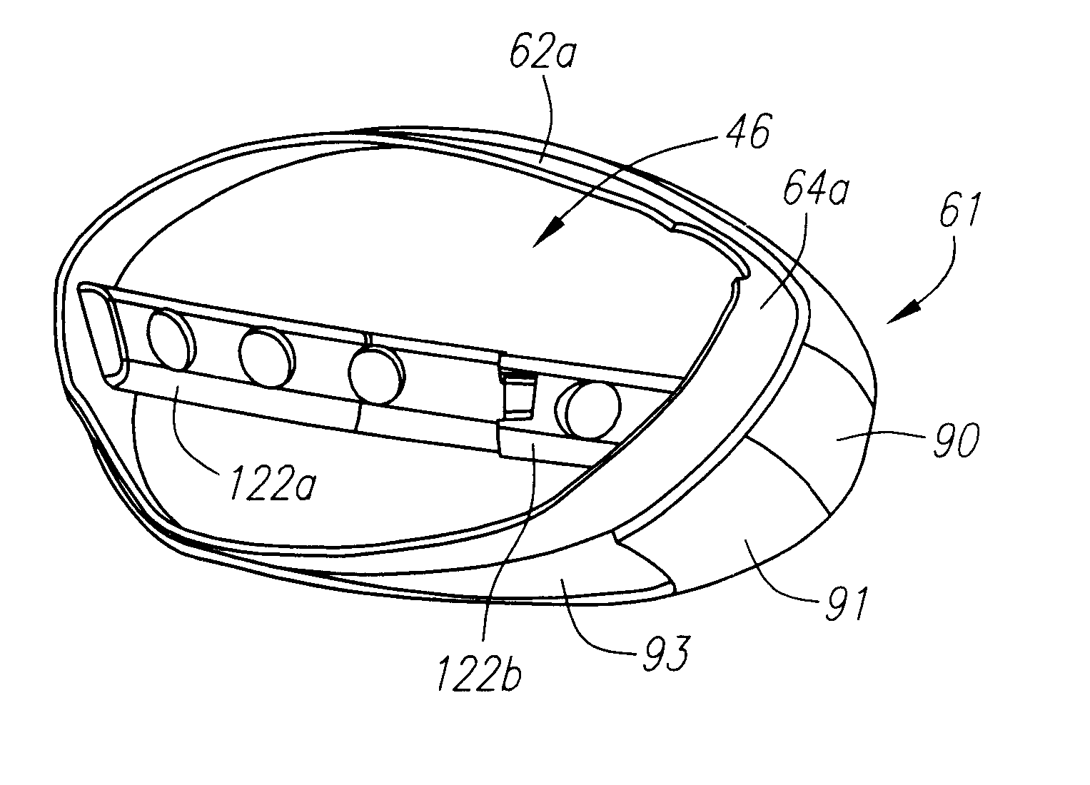
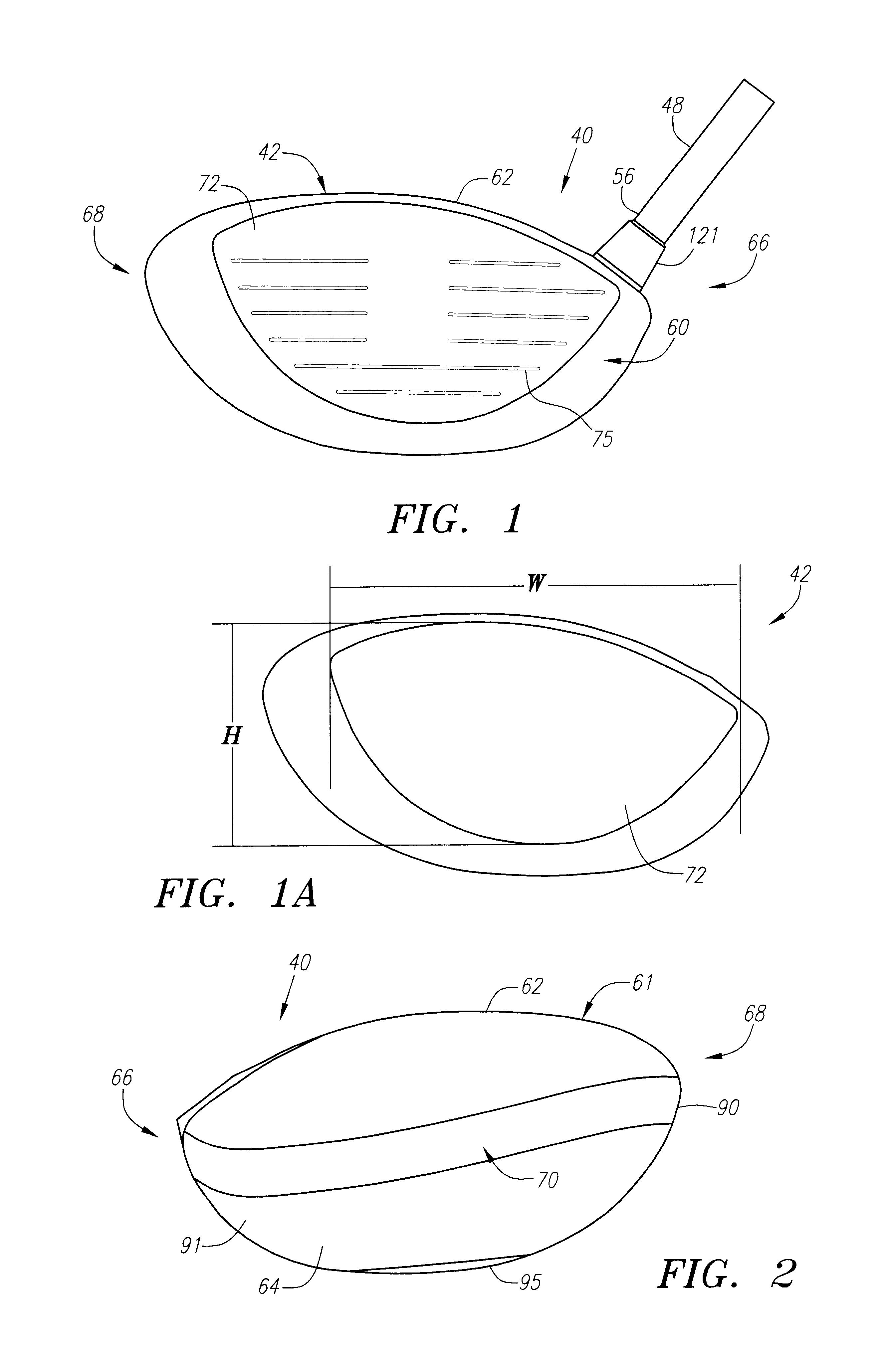
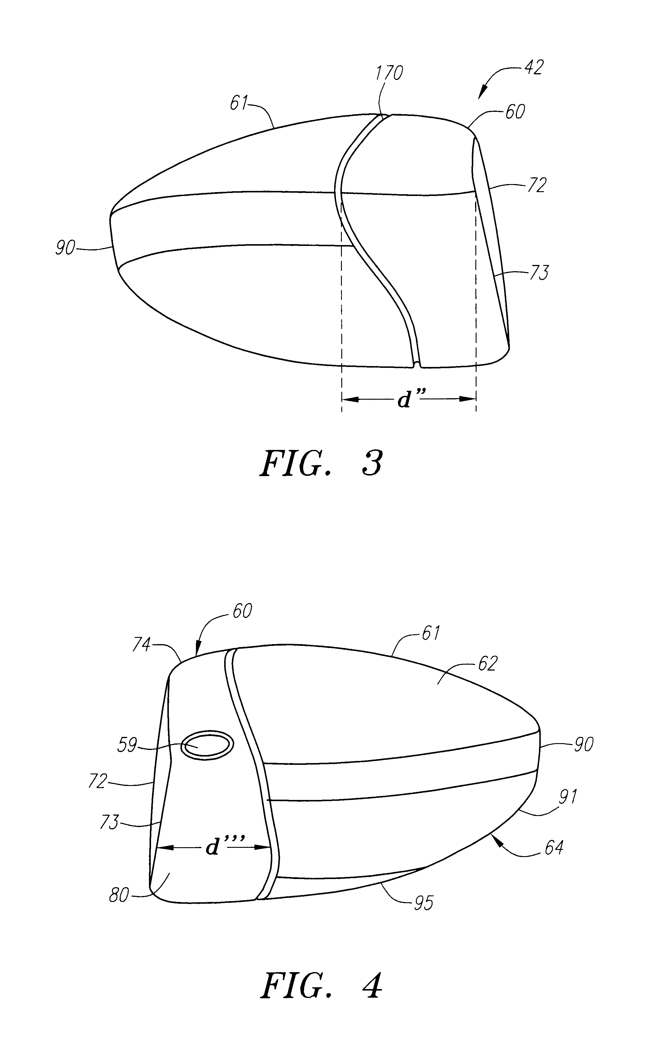
is a 430 cubic centimeter golf club head 42 with the total club weighing 270 grams. The face component 60 is composed of a cast titanium, Ti 6-4 material. The aft body 61 is composed of a plurality of plies of pre-preg. The golf club head 42 has a loft angle of eleven degrees and a lie of 54 degrees. The bulge radius is 11 inches and the roll radius is 10 inches. The vertical distance h of the club head of example 1 is 2.14 inches, and the distance w is 3.46 inches. Example 2 is a 510 cubic centimeter golf club head 42 with the total golf club weighing 285 grams. The face component 60 is composed of a forged titanium alloy material, Ti 10-2-3. The aft body 61 is composed of a plurality of plies of pre-preg. The bulge radius is 11 inches and the roll radius is 10 inches. The vertical distance h of the club head of example 2 is 2.54 inches, and the distance w is 3.9 inches. Example 3 is a 385 cubic centimeter golf club head 42 with the total golf club weighing 198 grams. The face comp...


PUM

PropertyMeasurementUnit
thicknessaaaaaaaaaa
thicknessaaaaaaaaaa
thicknessaaaaaaaaaa

Abstract

A golf club (40) having a club head (42) with a face component (60) and an aft body (61) is disclosed herein. The face component (60) has a striking plate portion (72) and a return portion (74). The aft-body (61) is composed of a crown portion (62), a sole portion (64) and optionally a ribbon section (90). The face component (60) is composed of a metal material, and the aft-body (61) is composed of a non-metal material such as a composite material or a thermoplastic material. The striking plate portion (72) preferably has an aspect ratio less than 1.7. The striking plate portion (72) preferably has concentric regions of thickness with the thickness portion in the center (102). The club head (42) has a volume in the range of 290 cubic centimeters to 600 cubic centimeters, a weight in the range of 165 grams to 300 grams, and a striking plate portion (72) surface area in the range of 4.00 square inches to 7.50 square inches. The golf club head (42) has a coefficient of restitution greater than 0.81 under test conditions such as the USGA test conditions specified pursuant to Rule 4-1e, Appendix II, of the Rules of Golf for 1998-1999.

Description

FEDERAL RESEARCH STATEMENT[Not Applicable]BACKGROUND OF INVENTION1. Field of the InventionThe present invention relates to a golf club head with a face component composed of a metal material, and an aft-body composed of a light-weight material. More specifically, the present invention relates to a golf club head with face component composed of a metal material for a more efficient transfer of energy to a golf ball at impact, and a non-metallic aft-body to control the mass distribution.2. Description of the Related ArtWhen a golf club head strikes a golf ball, large impacts are produced that load the club head face and the golf ball. Most of the energy is transferred from the head to the golf ball, however, some energy is lost as a result of the collision. The golf ball is typically composed of polymer cover materials (such as ionomers) surrounding a rubber-like core. These softer polymer materials having damping (loss) properties that are strain and strain rate dependent which are o...

Claims


Application Information

Patent Timeline
Patent Type & Authority Patents(United States)
IPC IPC(8): A63B53/02A63B53/04
CPCA63B53/02A63B53/0466B21J5/00B21K17/00C22F1/183C23F1/00C23F1/26A63B53/04A63B2053/0462A63B2053/0408A63B2053/0412A63B2053/0416A63B2053/0441A63B2053/0458A63B2053/0491A63B2209/023A63B2209/00A63B2053/0433A63B2053/0437A63B53/0412A63B53/0408A63B53/0462A63B53/0416A63B53/0437A63B53/0441A63B53/0433A63B53/0458A63B60/02A63B60/00
Inventor SORACCO, PETER L.HELMSTETTER, RICHARD C.HOCKNELL, ALANCACKETT, MATTHEW T.REYES, HERBERTMURPHY, JAMES M.GALLOWAY, J. ANDREWROLLINSON, AUGUSTIN W.
Owner TOPGOLF CALLAWAY BRANDS CORP
Why Eureka
Try Eureka