Optical system for diffusing light

a technology of optical system and light, applied in the field of optical system, can solve the problems of poor efficiency of typical commercially available screens with lenticular array, 30% or less, undesirable color banding and white and dark lines, expensive and unaesthetic,

Inactive Publication Date: 2003-06-24
UNIVERSITY OF ROCHESTER
View PDF5 Cites 17 Cited by
  • Summary
  • Abstract
  • Description
  • Claims
  • Application Information

AI Technical Summary

Problems solved by technology

Typical commercially available screens with a lenticular array have poor efficiency, 30% or less, and have undesirable color banding and white and dark lines at the edges of the pattern due to the diffraction effect of the lenslet array.
While diffusing reflectors are effective, they are expensive and unaesthetic.
However, such light diffused through frosted glass is often not as uniform as desired.
Although cascades of a grating and a diffuser have been proposed in other areas, they have been limited to the analysis of coherence properties, such as discussed in K. M. Jauch and H. P. Baltes, "Coherence of radiation scattered by gratings covered by a diffuser.
The prior art cascades of a grating and a diffuser do not produce over a wide angle the uniform diffused light needed for illumination and display applications.
The tradeoff in efficiency with lobe width is most severe for the conical surface showing a 10% loss at only 10.degree. lobe width.
The parabolic diffuser, however, can provide a 50.degree. lobe width with less than 5 % reduction in efficiency.
The frosted glass and Armour etched diffuser are significantly less efficient yet have a similar lobe width.
Thus, they are less desirable for use as a projection screen.
Although all 23 orders can be optimized, the higher orders have large angular separations and will not yield satisfying results.

Method used


Image

  • Optical system for diffusing light
  • Optical system for diffusing light
  • Optical system for diffusing light

Examples


example 2

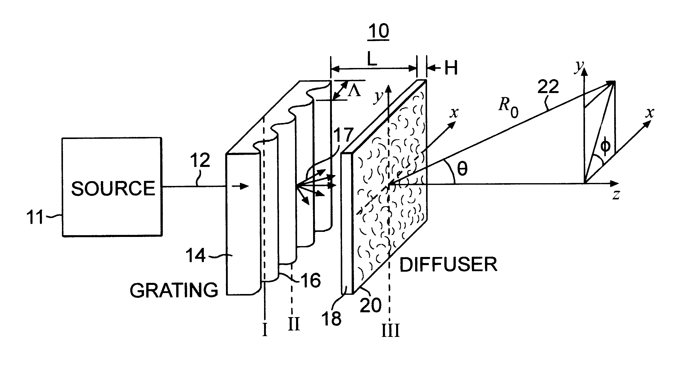
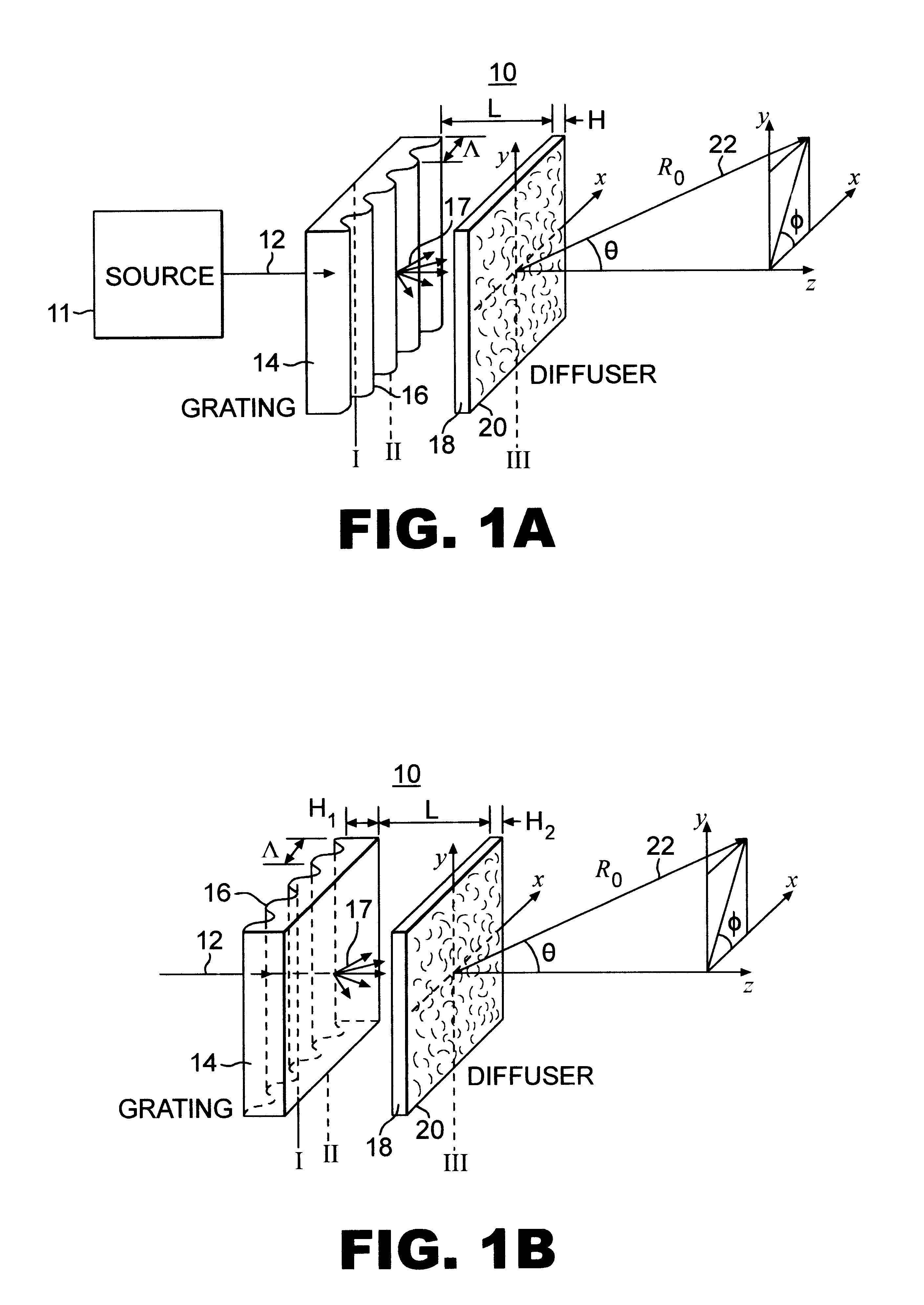
The optimum diffraction orders provided by the diffraction grating 14 in system 10 may be provided by more than one diffractive element, such as shown for example in the system 28 of FIG. 11A. Multiple diffraction gratings can be used to provide additional diffraction orders to the diffuser or when it is difficult to fabricate a single grating having the desired number of orders at the desired multiple wavelengths, such as more than 5 or 6 optimum orders at three wavelengths. System 28 operates the same as system 10 except that two diffraction gratings 14a and 14b are used with diffuser 18, instead of a single diffraction grating. Diffraction gratings 14a and 14b may be on different optical elements or two surfaces of the same optical element. In this example, a second grating 14b with a 15.degree. diffraction angle is added to the system of the previous example, where grating 14a is a 5.degree. grating oriented as the grating shown in FIG. 1A, and grating 14b and diffuser are orien...


PUM


Abstract

An improved optical system is provided for diffusing light uniformly over a wide angle, including, a diffractive element for diffracting light received by the system in multiple diffraction orders, and a diffusing element which diffuses the diffracted light. The diffractive element provides diffracted light having an angular distribution of intensities over the diffraction orders which is correlated to the power spectrum of the diffusing element such that the system produces a predetermined intensity distribution of diffused light. The diffraction period of the diffractive element is selected such that the angular separation between the zeroeth and first diffraction orders is approximately one-half the angular extent of the full-width-at-half-maximum of the power spectrum of the diffusing element. The strengths of the diffraction orders are selected such that the combination of diffused light from each diffractive order provides uniformity in the intensity of the diffused light from the system.

Description

DESCRIPTION1. Field of the InventionThe present invention relates to an optical system (and method) for diffusing light, and relates particularly to, an optical system having a diffractive element and a diffusing element, which diffuses light diffracted from the diffractive element. The invention is especially suitable for diffusing light for a projection television (TV) or display screen, or diffusing light for a window, skylight, light bulb or light tube, such that the diffused light has a uniform intensity distribution over a wide angle.2. Background of the InventionOptics for diffusing light is typically used for large screen projection TV's, and includes a lenticular array consisting of vertically oriented cylindrical lenslets formed in a plastic sheet. The array distributes the light horizontally by an angular amount determined by the numerical aperture of the individual lenslets. Typical commercially available screens with a lenticular array have poor efficiency, 30% or less,...

Claims


Application Information

Patent Timeline
Patent Type & Authority Patents(United States)
IPC IPC(8): G02B27/42G02B5/02G02B5/18G02B27/44
CPCG02B5/0221G02B5/0252G02B27/425G02B5/1814G02B5/0278
Inventor GEORGE, NICHOLASSCHERTLER, DONALD J.
Owner UNIVERSITY OF ROCHESTER
Why Eureka
Try Eureka