Method and sensor arrangement for measuring temperature and strain using an optical fiber embedded in a cover layer on a substrate

a technology of optical fiber and cover layer, applied in the direction of optical radiation measurement, force/torque/work measurement apparatus, instruments, etc., can solve the problems of difficult or impossible to separate the influences, the effort and expense of inspection and upkeep become significantly increased, and the temperature and strain are difficult or impossible to determine separately

Inactive Publication Date: 2003-07-01
AIRBUS OPERATIONS GMBH
View PDF16 Cites 58 Cited by
  • Summary
  • Abstract
  • Description
  • Claims
  • Application Information

AI Technical Summary

Problems solved by technology

When an aircraft, or generally any vehicle, approaches the end of its useful operating life, the effort and expense of inspection and upkeep become significantly increased.
This fact also underlies the basic problem of all known temperature and strain measurements using fiber optic sensors, for all types of structural sensor arrangements, namely that the strain and the temperature have a basic and fundamental influence on the values or parameters that can be determined using available measuring technology.
Thus, it is difficult or impossible to separately determine the temperature and the strain, because it is difficult or impossible to separate the influences that the temperature has on the strain, and the combined influences that the temperature and the strain both have on the measured parameters.
The above mentioned sensor system, however, suffers the disadvantage that it apparently only applies to fiber optic Bragg grating sensors (FBGS) integrated directly into fiber reinforced composite structural components.
This fact has significant negative effects on the mechanical characterizing values of the structure under some circumstances, and on the effort and expense of fabrication thereof, and will not be practically acceptable to a person of ordinary skill in the art.
However, due to questionable accuracy of the location and fixing of the fiber, which is to be point-wise exactly fixed on the substrate in the adhesion process using the paint or paint-on coating, it seems impossible to avoid an adhesion of the adhesive film onto the substrate while fixing the fibers.
In this context, pulling-off the foil without leaving residual adhesive on the substrate can probably not be achieved.
It also seems that the apparatus that is used as an auxiliary aid for fixing the fibers on the perforated film or foil, is too complicated and thus subject to malfunction or breakdown.

Method used


Image

  • Method and sensor arrangement for measuring temperature and strain using an optical fiber embedded in a cover layer on a substrate
  • Method and sensor arrangement for measuring temperature and strain using an optical fiber embedded in a cover layer on a substrate
  • Method and sensor arrangement for measuring temperature and strain using an optical fiber embedded in a cover layer on a substrate

Examples


Embodiment Construction

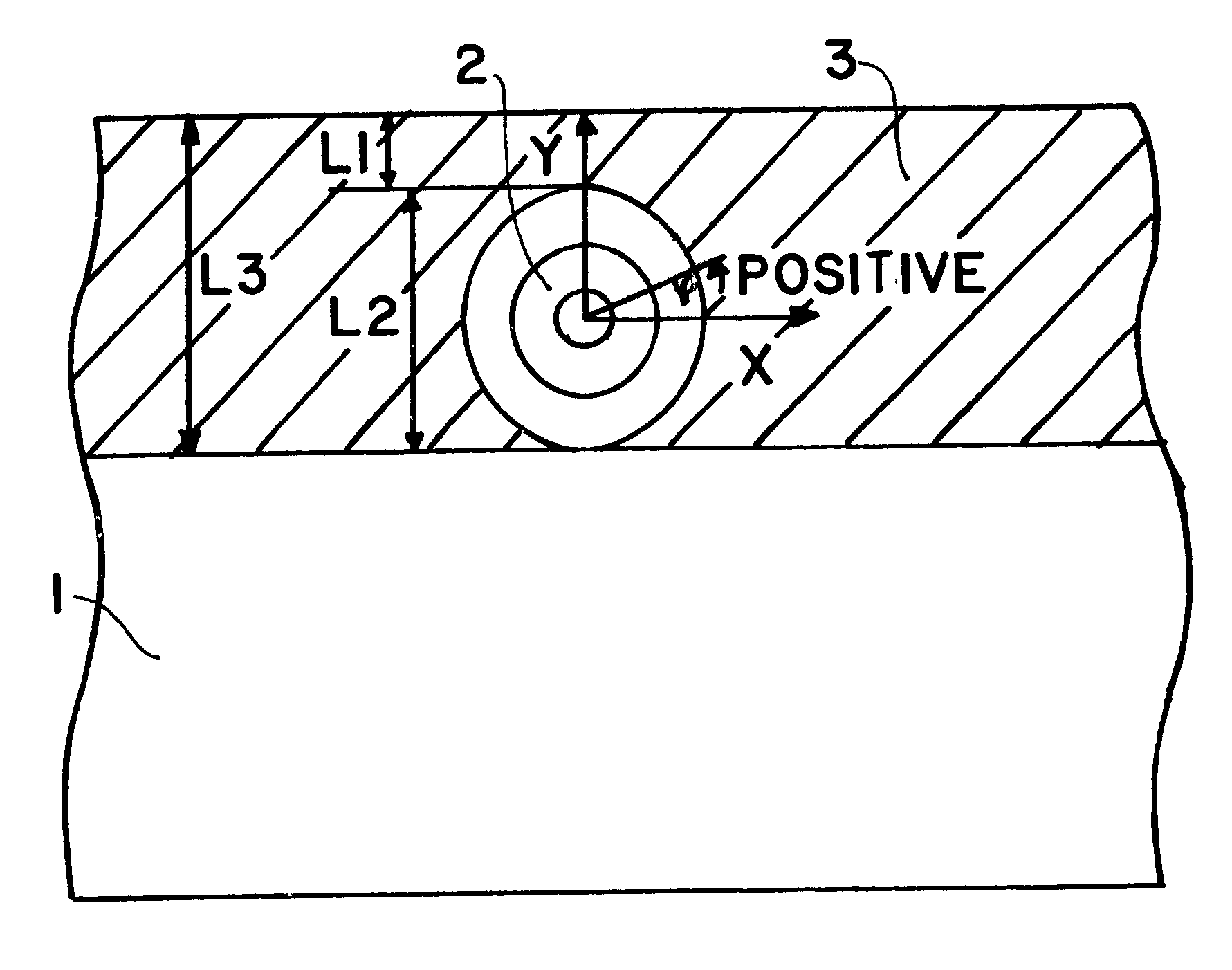
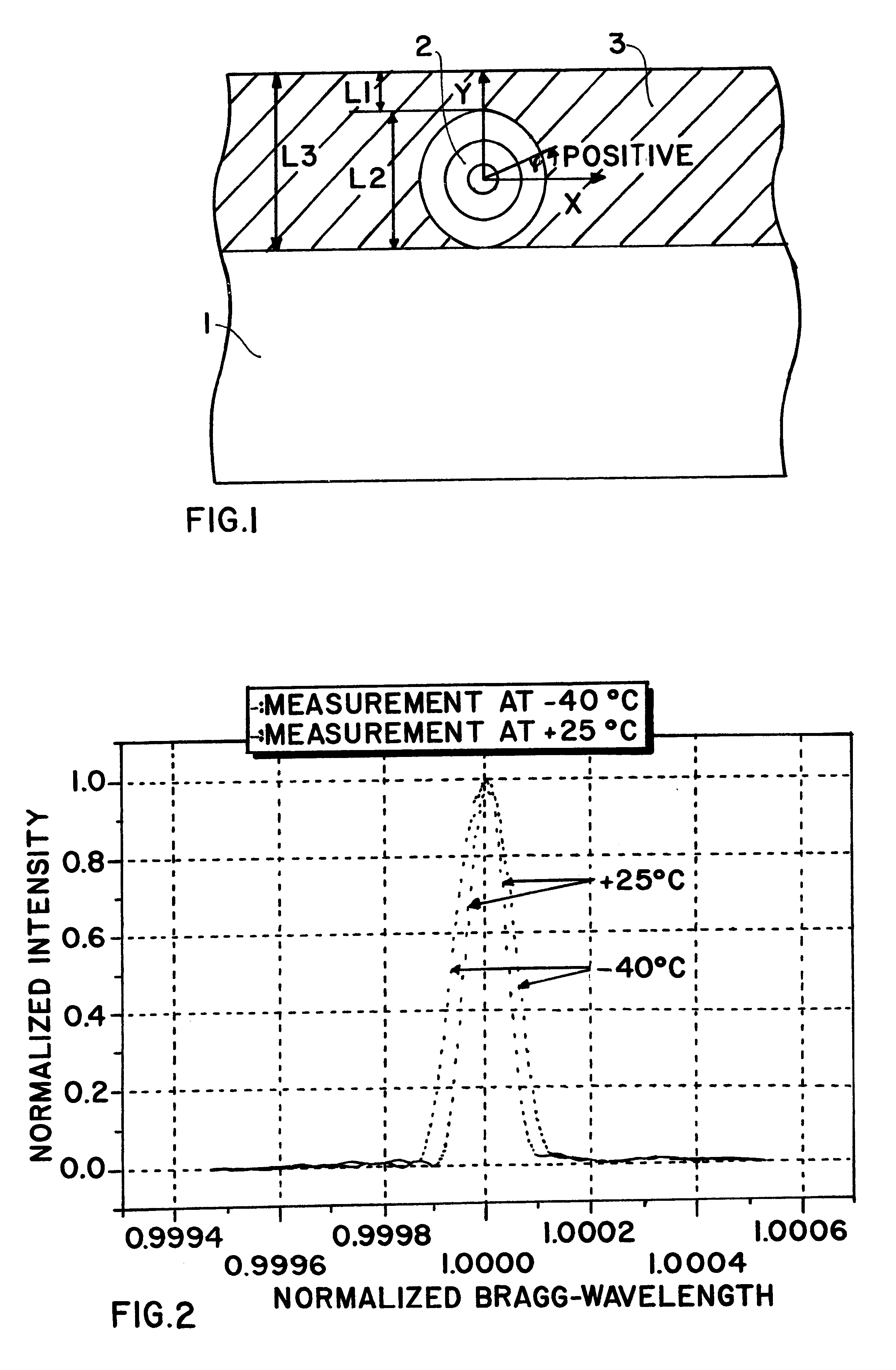
As schematically shown in FIG. 1, an example embodiment of the sensor arrangement according to the invention comprises a substrate 1 made of metal, synthetic plastic, or ceramic, such as aluminum, a carbon fiber-reinforced composite, a graphite fiber reinforced composite, a glass-fiber reinforced composite, Kevlar, or a Kevlar based material such as a Kevlar based composite material. The substrate 1 may be essentially any pre-existing structural component of which the surface strain and temperature is to be measured and monitored. The sensor arrangement further comprises at least one optical fiber 2 applied onto the surface of the substrate 1. The optical fiber 2 may be referred to as an optical fiber, a light conductor fiber, a light conductor, or an optical wave guide. The arrangement further comprises a cover layer 3 that is applied onto the substrate 1 and covering the optical fiber 2 as a protective surface coating. The cover layer 3 may be a lacquer, paint, enamel, varnish, re...


PUM

PropertyMeasurementUnit
temperaturesaaaaaaaaaa
Bragg wavelengthaaaaaaaaaa

Abstract

In a sensor arrangement for sensing temperature and strain, an optical fiber with a Bragg grating therein is arranged on a substrate and embedded in a cover layer. The fiber is initially adhered onto an adhesive carrier, which then positions and applies the fiber onto the substrate. The fiber is point-wise fixed onto the substrate by a binder applied through holes in the adhesive carrier. Next, the carrier is stripped off to leave the fiber on the substrate. A cover layer is applied over the fiber and the substrate. Temperature and strain variations are transmitted from the cover layer into the fiber as non-circularly-symmetrical strains. The strain and temperature can be independently determined using this single sensor, by feeding quasi-depolarized light into the fiber and measuring the overlapping birefringent reflections from the Bragg grating. The full width at half maximum value indicates the temperature, while the Bragg wavelengths indicate the strain and the temperature.

Description

PRIORITY CLAIMThis application is based on and claims the priority under 35 U.S.C. .sctn.119 of German Patent Application 100 04 384.4, filed on Feb. 2, 2000, the entire disclosure of which is incorporated herein by reference.The invention relates to an arrangement and a method for detecting and measuring strain and temperature and variations thereof, of a cover layer applied on a substrate, as well as to a method of making such a sensor arrangement. The sensor arrangement uses only a single sensor for separately determining the strain and the temperature and the variations thereof, of certain portions of surface coating layers, and achieves an application of optical sensors that is protected from outside environmental influences by being integrated into the surface coating layer.BACKGROUND INFORMATIONIt is becoming increasingly important to monitor, observe, control, and regulate various structural characteristics in the fields of conventional transport systems for air travel and s...

Claims


Application Information

Patent Timeline
Patent Type & Authority Patents(United States)
IPC IPC(8): G01M11/08G01L5/00G01K11/00G01K11/32G01K1/14G01B11/16G01K11/12G02B6/02G02B6/024G02B6/036
CPCG01K11/3206G01L5/0047G01M11/086
Inventor GLEINE, WOLFGANGTRUTZEL, MICHAEL
Owner AIRBUS OPERATIONS GMBH
Why Eureka
Try Eureka