Power transmission system for a Faraday cage power source

a power transmission system and faraday cage technology, applied in transmission, line transmission details, aperture leaage reduction, etc., can solve the problem of not reducing the shielding provided, and achieve the effect of high shielding level

Inactive Publication Date: 2003-07-22
NORTEL NETWORKS LTD
View PDF2 Cites 25 Cited by
  • Summary
  • Abstract
  • Description
  • Claims
  • Application Information

AI Technical Summary

Benefits of technology

Advantageously, by providing conductive contact between said transmission element and said Faraday cage, the shielding providing by the Faraday cage is not unduly compromised. A sufficiently good contact, for example, enables the Faraday cage to provide a very good level of shielding.
Preferably, said low-pass filter filters out power disturbances provided to said first power source. Advantageously, this prevents the first power source from being affected by power surges or suffering damage due to high energy EMI pulses coupling to the power source of said first power source.
A waveguide may be attached to said Faraday cage in the vicinity of an aperture through which said transmission element passes, said wave-guide being adapted to prevent further propagation of electromagnetic radiation of a predetermined wavelength away from said aperture in said Faraday cage.
Advantageously, such a Faraday cage prevents electromagnetic transmissions emanating from within the cage from being detected externally which, for example, might provide information on the content of such transmissions and the location of the equipment.
Advantageously, the isolation of the power supply therefore enables Faraday cages to be constructed which are particularly suited to environments where confidential information is being transmitted. It is possible to elicit information from electromagnetic emissions, and by enabling the construction of Faraday cages which provide a high shielding level against electromagnetic radiation associated with the transmission of information, protection against detection can be provided for such confidential information.

Problems solved by technology

The system transfers power from an external power source to an internal power generator and yet does not mitigate the shielding provided by the Faraday cage against EMI disturbances.

Method used


Image

  • Power transmission system for a Faraday cage power source
  • Power transmission system for a Faraday cage power source
  • Power transmission system for a Faraday cage power source

Examples


first embodiment

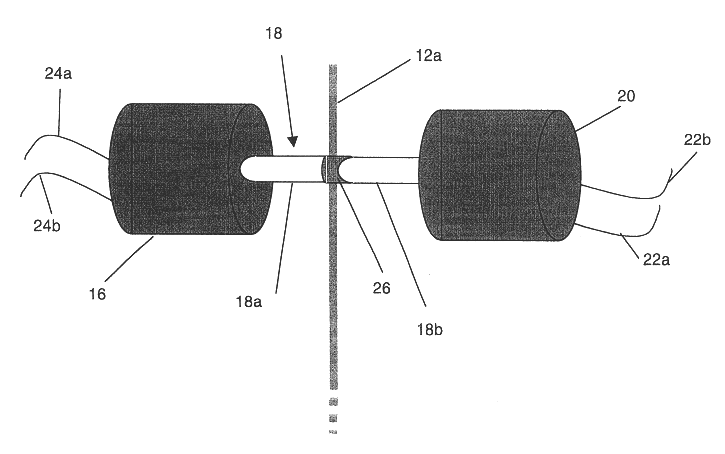
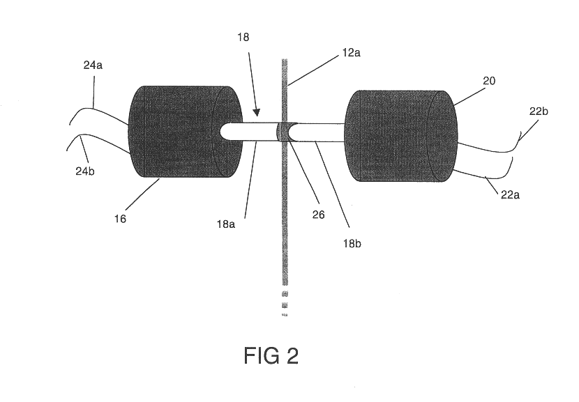
FIG. 2 of the accompanying drawings illustrates a transmission system according to the invention. In FIG. 2, the transmission system transfers power via a transmission element 18 from a first power source 16 located outside Faraday cage 12 through an aperture in a wall 12a of the Faraday cage to drive a second power source 20. Second power source 20 provides power to equipment (not shown) housed within the Faraday cage 12.

The transmission element 18 transfers energy without using a conductive electrical path by providing energy in a mechanical form through the wall 12a to the second power source 20. The second power source 20 converts the mechanical energy it receives from the transmission element 18 into a form suitable for powering the equipment housed within the Faraday cage 12. For example, second power source 20 may comprise an electrical generator and provide electrical power or may comprise a battery charger to power batteries which provide power to electrical equipment. Alte...

second embodiment

FIG. 4A shows the invention which modifies the shape of the boundary region 30 of the drive shaft shown in FIG. 3. Conductive annular flange sections 34, 36 are provided on the drive shaft 18 to overlap the edge of the aperture in the Faraday cage wall. This creates a boundary region 30 which has a U-bend type configuration. The drive shaft is thus able to engage with the edge 28 of the Faraday cage 12 and remove any line-of-sight aperture through the wall of the Faraday cage. In FIG. 4A, only a U-bend configuration is shown, but a series of U-bend type configurations or equivalently a tongue / groove type-configuration may be provided when this is feasible for a Faraday cage construction.

in the embodiment shown in FIG. 4A the annular flange sections 34, 36 provided on at each end of the conductive region 20 form exterior and interior rims around the wall of the Faraday cage. Alternatively, one or both flanges 34, 36 may be omitted and instead an annular groove may be formed in the co...

third embodiment

As is apparent to one skilled in the art, the configuration of the draft shaft 18 and Faraday cage 12 need not be symmetrical about the cage surface, and the flange portions 34, 36 may be present only on one side of the cage wall, and / or may be provided with further engaging features such as FIG. 4B shows. In FIG. 4B, an example of a further modification to a flange and the Faraday cage wall 12a around the region of the drive shaft 18 is shown. In this third embodiment, annular protrusions 34a formed in annular flange 34 extend into an annular cavity 12b formed in the wall of the Faraday cage 12.


PUM


Abstract

A transmission system is provided for a power source to transfer power to equipment housed within a Faraday cage. The transmission system transfers energy along a non-conductive path yet remains in conductive contact with the Faraday cage. This prevents EMI disturbing electrical power provided within the Faraday cage and damaging equipment housed within the cage. The transmission system enables mains power to be transmitted to equipment housed within the Faraday cage without the need to provide conventional electric filters. The performance of the Faraday cage in shielding electromagnetic radiation is not compromised. Nor is the ability of the Faraday cage to shield electromagnetic radiation generated by communications equipment within the cage compromised.

Description

The present Invention relates to a transmission system for providing power to equipment housed in a Faraday cage, to a power source for such equipment, and to a Faraday cage provided with such a power source. Particularly, but not exclusively, the transmission system enables power to be provided to communications equipment housed in a Faraday cage which requires shielding against electromagnetic interference and leakage up to at least 5 GHz.BACKGROUND TO THE INVENTIONEquipment which is sensitive to electromagnetic interference is often protected by isolating apparatus within a conductive shell, or Faraday cage. Faraday cages are also used to retain electromagnetic radiation which is emitted by equipment. Electromagnetic field theory describes how electromagnetic waves interact with a conductive surface shell. Essentially, the shell distributes the electrical field around the shell surface, but not through the shell surface. Accordingly, electromagnetic fields generated outside a Far...

Claims


Application Information

Patent Timeline
Patent Type & Authority Patents(United States)
IPC IPC(8): H05K9/00
CPCH05K9/0018
Inventor TURTON, BRIAN C
Owner NORTEL NETWORKS LTD
Why Eureka
Try Eureka