Method and system of modifying integrated circuit power rails

a technology of integrated circuit power rails and power rails, which is applied in computer aided design, semiconductor/solid-state device details, instruments, etc., can solve the problems of increasing the number of power shapes, affecting the storage and performance of layout related tools, and unable to conn

Inactive Publication Date: 2003-07-22
PERLEGEN SCIENCES INC +1
View PDF1 Cites 51 Cited by
  • Summary
  • Abstract
  • Description
  • Claims
  • Application Information

AI Technical Summary

Benefits of technology

Reducing congestion and improving pin accessibility increases the ability to complete automatic wiring successfully. Thus, there has arisen a need for an efficient method of modifying power shapes to reduce congestion and improve wireability in an application specific integrated circuit (ASIC) design.
It is therefore one object of this invention to provide an automatic physical design tool to reduce wiring congestion and improve wireability in an ASIC design that is independent of the underlying design methodology.
It is yet another object of the invention to provide an automatic physical design tool that improves pin accessibility and therefore increases wireability in an ASIC design that is independent of the underlying design methodology.
Another embodiment of the invention includes an alternative power pattern for the power rails to relieve wiring congestion in affected areas of an ASIC design. This embodiment of the invention determines areas of the design that benefit by changing the power rail pattern from an initial pattern to an alternative pattern such as stitches or staples. The second embodiment can operate in an iterative manner to achieve a desired wireability result.

Problems solved by technology

However, this dramatically increases the number of power shapes, which impacts the storage and performance of the layout related tools.
Additionally, input / output LSTs (pins or logic service terminals) of placed library cells sometimes become blocked by the power rails during power routing, making connection impossible.
The M2 power staple pattern, when compared with the other M2 power patterns of stitches or rails, is the least electrically robust though not significantly due to other pinch points in the power grid on other levels.

Method used


Image

  • Method and system of modifying integrated circuit power rails
  • Method and system of modifying integrated circuit power rails
  • Method and system of modifying integrated circuit power rails

Examples


first embodiment

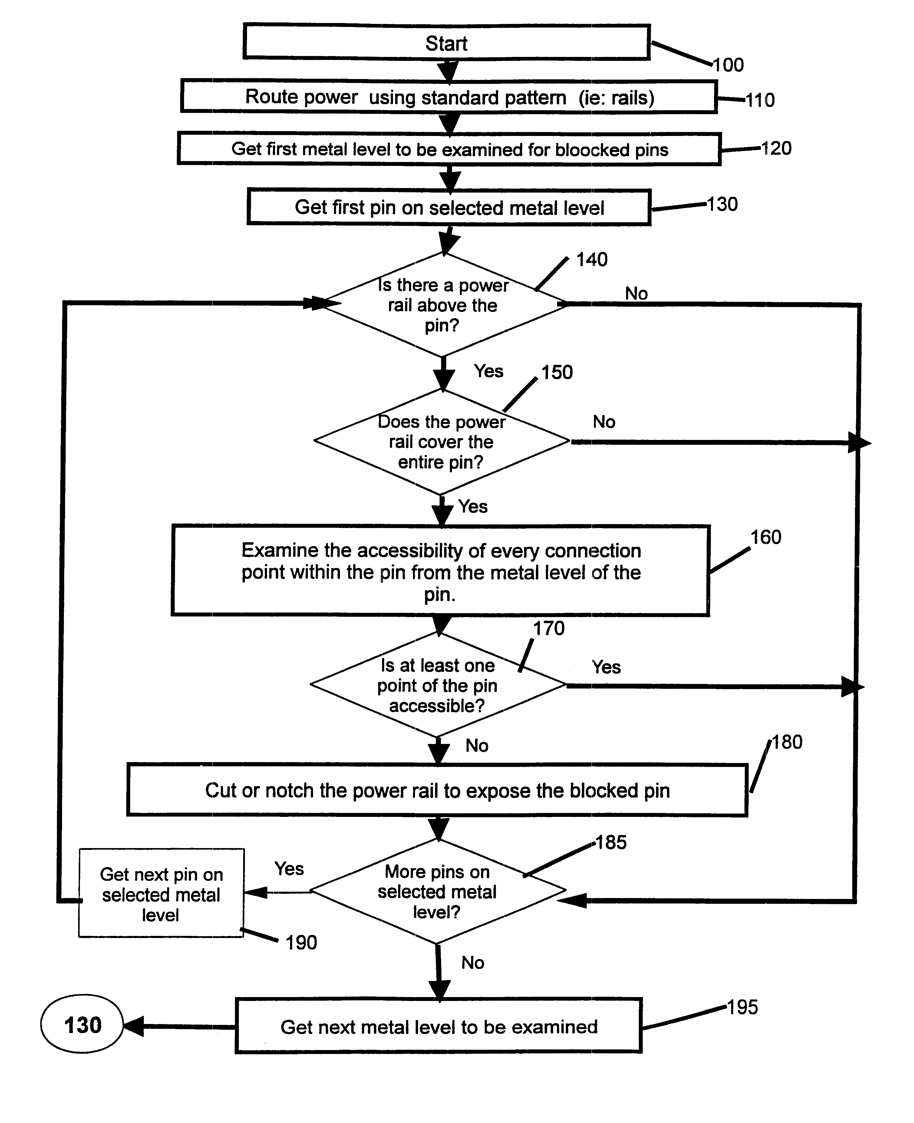
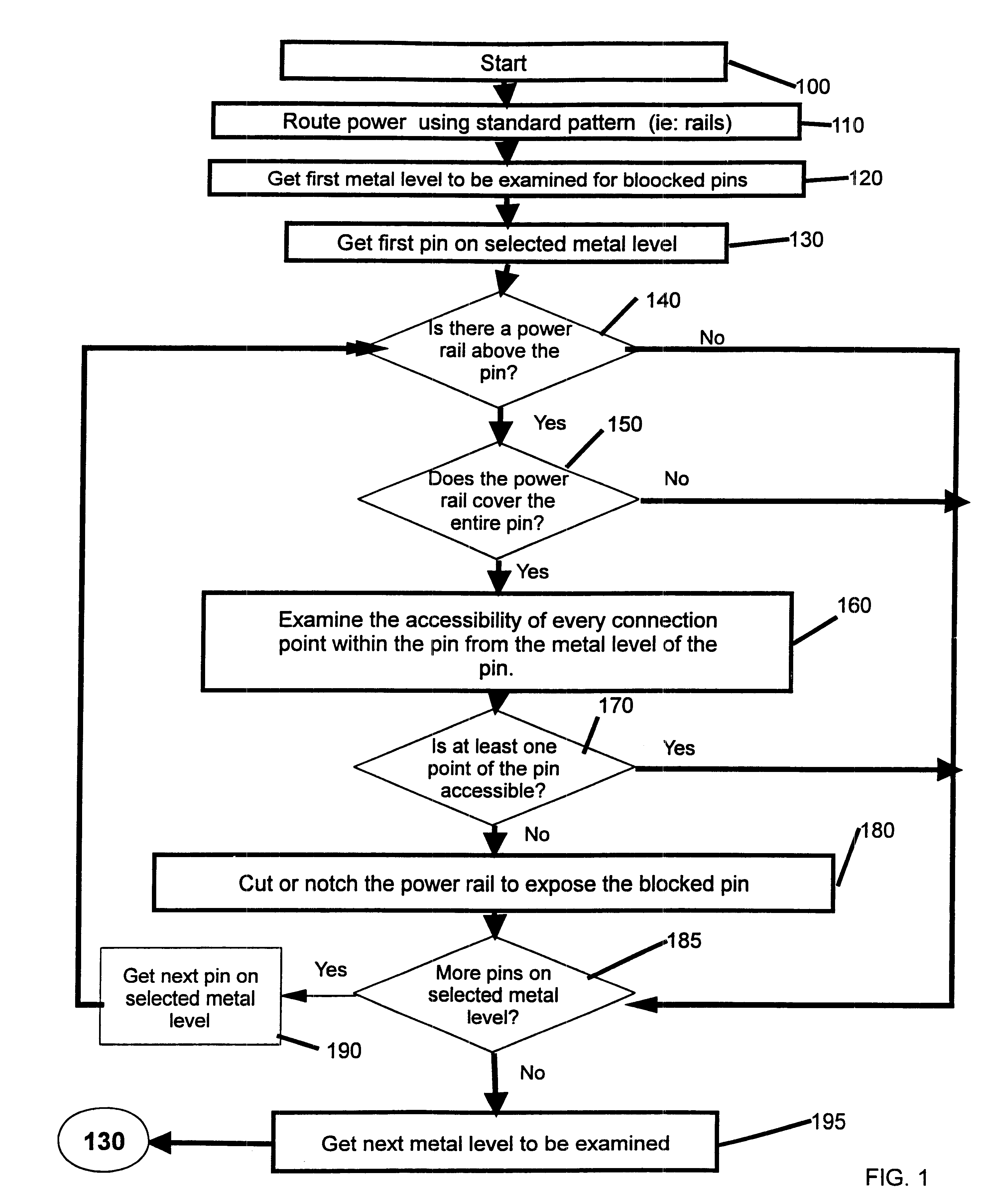
The first embodiment of the invention is shown in FIG. 1 as follows and is illustrated with an exemplary power rail design for one polarity of power as shown in FIGS. 2-6. This embodiment of the invention improves M1 pin accessibility (and therefore design wireability), in a power rail design by cutting or notching the inhibiting M2 power rails while maintaining their connection to standard M1 and M3 power rails and maintaining the integrity of the power grid.

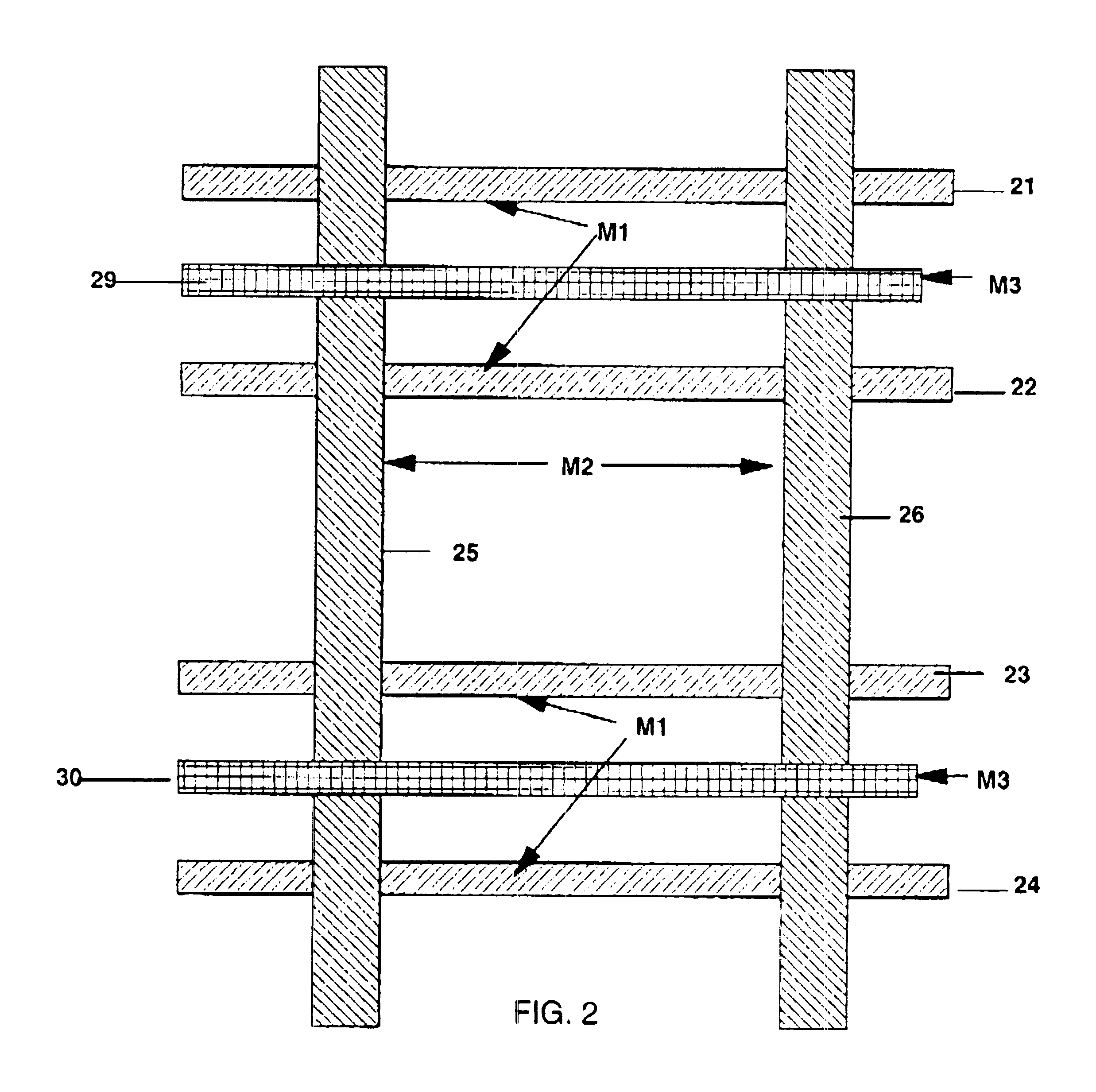
In FIG. 2, an example power rail placement for one polarity of power is shown wherein the M2 power rails 25 and 26 connect by power vias to M1 power rails 21, 22, 23 and 24 and M3 power rails 29 and 30. FIG. 3 shows the power rails of FIG. 2 wherein the M2 power rail 25 blocks access to the M1 pin 50 and the M2 power rail 26 blocks access to the M1 pin 55. FIG. 4 shows M2 power rail 25 cut to expose the M1 pin 50. FIG. 5 shows M2 power rail 26 notched or trimmed back to expose the M1 pin 55.

The embodiment of the invention start...

second embodiment

This second embodiment of the invention shown in FIG. 9 provides an alternative for modifying the power rails so as to relieve wiring congestion in affected areas of an ASIC design. This is done by determining area on any metal level that benefits by changing a power pattern from the initial pattern to an alternative pattern after finding congested areas using a congestion analysis tool or after detail signal routing. If after detail signal routing uncompleted connections exist, changing to an alternative pattern may improve the routing of the uncompleted connections. A tool that is used within ChipBench to determine wiring congestion is a hierarchical design planner (HDP) global router tool. This tool takes a placed ASIC design and a given set of metal layers, and it partitions each metal layer into a grid whose edges are arbitrarily, but equally, spaced. Then, the HDP global router tool connects pins with estimated wires as determined by the design while trying to minimize the num...


PUM


Abstract

A method and system for modifying power rails of an integrated circuit having improved wireability. This is accomplished by initially generating a power railing design of the integrated circuit into a three-dimensional rail based model. Next, analysis of the design is performed as to placement of the power rails in relation to neighboring elements that affects a predefined wireability. Finally, modification of a segment of each power rail that affects wireability is performed so that required power supply to the neighboring elements (e.g., pins, rails etc.) remains unaffected.

Description

1. Field of the InventionThis invention relates to the physical design of semiconductor integrated circuits, and more particularly to a physical design methodology and tools which automatically modify power shapes to improve overall wireability in congested areas and provide access to inaccessible pins or logic service terminals (LSTs).2. Description of the Related ArtDuring physical design of integrated circuits, automatic placement tools are typically used to obtain placement for functional library cells in the design. Automatic power routing tools are typically used to route the power rails of the design. Congestion analysis tools are used to analyze the resulting design after placement and power routing has been completed and prior to final signal wiring. Congestion analysis gives an early indication of the likely success of signal wiring. International Business Machines Corporation of Armonk, N.Y., USA provides placement, power routing, congestion analysis and detail wiring in ...

Claims


Application Information

Patent Timeline
Patent Type & Authority Patents(United States)
IPC IPC(8): G06F17/50H01L23/52H01L23/528
CPCG06F17/5077H01L23/5286H01L2924/0002H01L2924/00G06F30/394
Inventor DARDEN, LAURA R.GOULD, SCOTT W.RYAN, PATRICK M.URISH, STEVEN J.
Owner PERLEGEN SCIENCES INC
Why Eureka
Try Eureka