Load drive circuit having low voltage detector

a low-voltage detector and drive circuit technology, applied in the direction of contact mechanisms, pulse techniques, instruments, etc., can solve the problems of increased cost and large parts, noise generation, and light turning on and off,

Inactive Publication Date: 2003-08-05
DENSO CORP +1
View PDF15 Cites 13 Cited by
  • Summary
  • Abstract
  • Description
  • Claims
  • Application Information

AI Technical Summary

Problems solved by technology

Therefore, it is necessary to adopt an element of large allowable loss and an element of high withstand voltage so that cost is increased and parts are large-sized.
Further, in a period in which the MOSFET 4 is in the oscillating state, there may be a problem that chattering is generated in a relay switch when the load 2 is a relay coil.
When the load 2 is a light, there may be also a problem that the light is turned on and off.
Further, constant voltage control is not performed.
Therefore, temporary reduction in the inputted power voltage does not easily appear in the output.
Accordingly, temporary voltage variation generated in turning the load on and off is not easily detected by the above characteristics of the charge pump circuit.
As a result, oscillating state alternately repeating turning on and off of the MOSFET 15 is not easily caused.

Method used


Image

  • Load drive circuit having low voltage detector
  • Load drive circuit having low voltage detector
  • Load drive circuit having low voltage detector

Examples


third embodiment

A fourth embodiment adding a change to the third embodiment will next be explained with reference to FIGS. 8 and 9. In FIG. 8 showing the electric construction of a load drive circuit, the same constructional portions as FIG. 6 are designated by the same reference numerals, and different constructional portions will be explained here.

The load drive circuit 54 shown in FIG. 8 differs from the load drive circuit 48 shown in FIG. 6 in the construction of a charge pump circuit. The charge pump circuit 55 of the load drive circuit 54 is constructed by a booster circuit 55a having the same construction as the charge pump circuit 17 shown in the first to third embodiments, and a control circuit 55b for controlling a voltage raising operation of this booster circuit 55a.

The control circuit 55b is constructed by a detecting circuit of the battery voltage Vb, a reference voltage generating circuit, and a comparator (which are not shown in the drawings). The reference voltage generating circui...

first embodiment

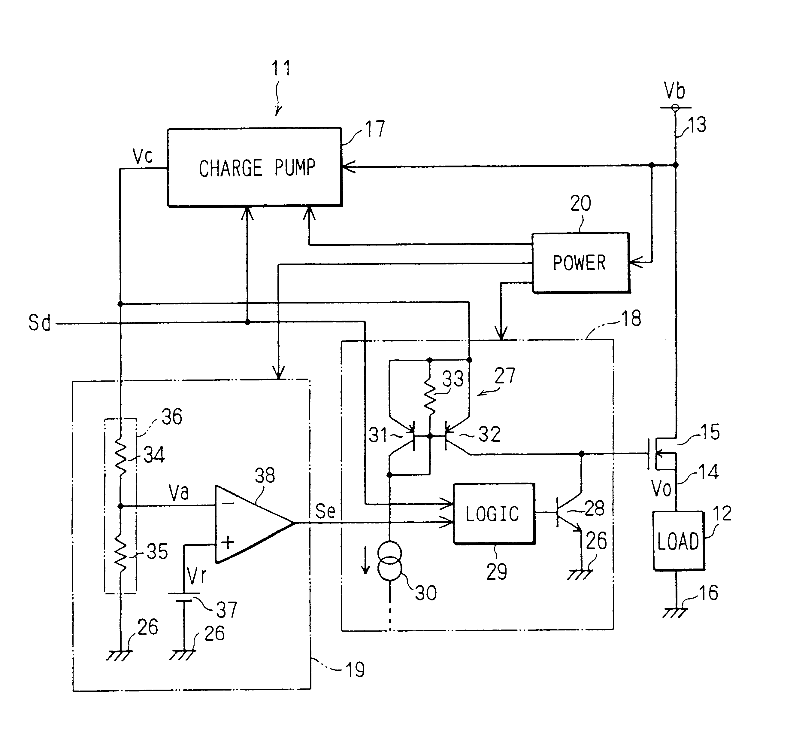
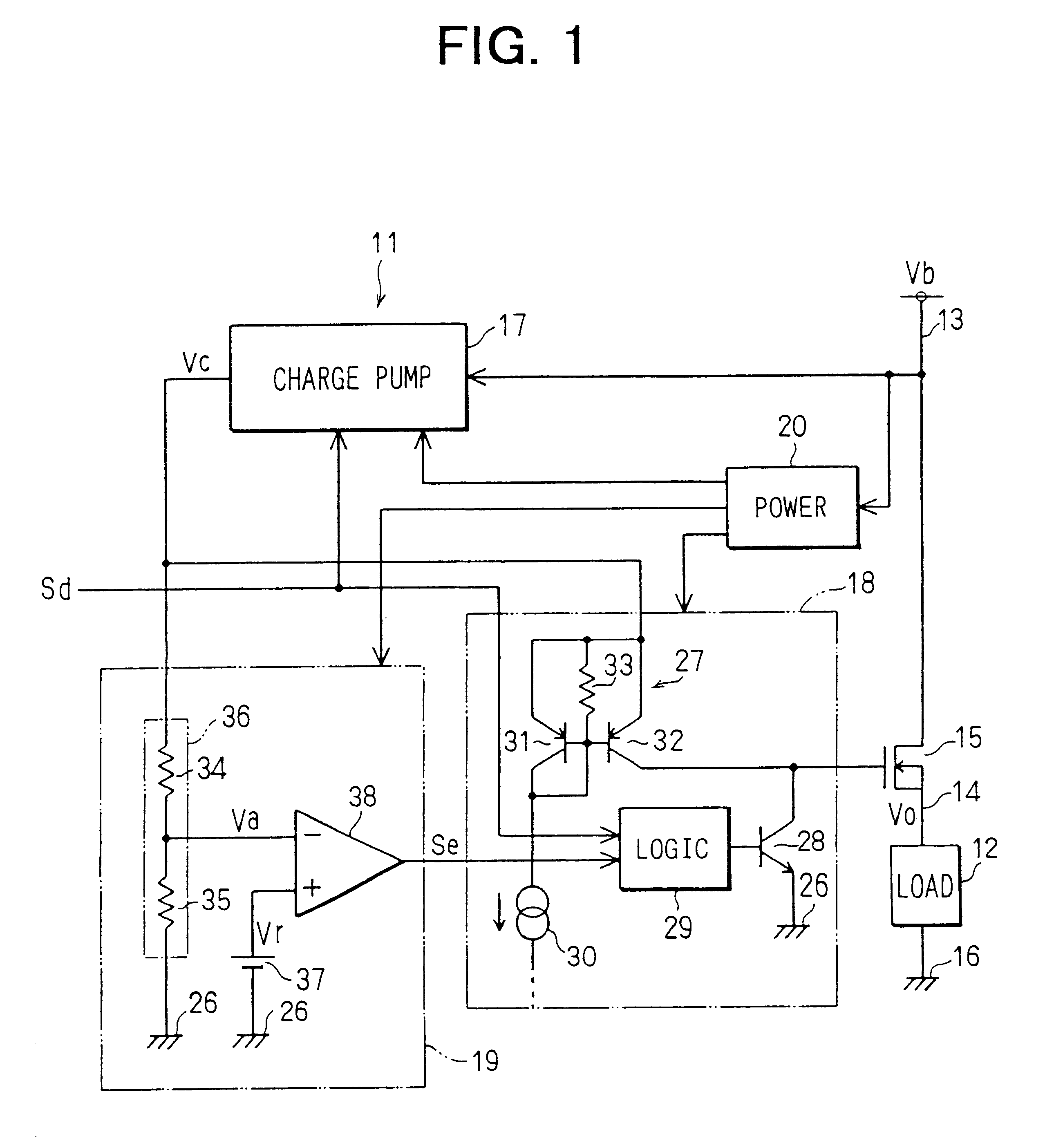
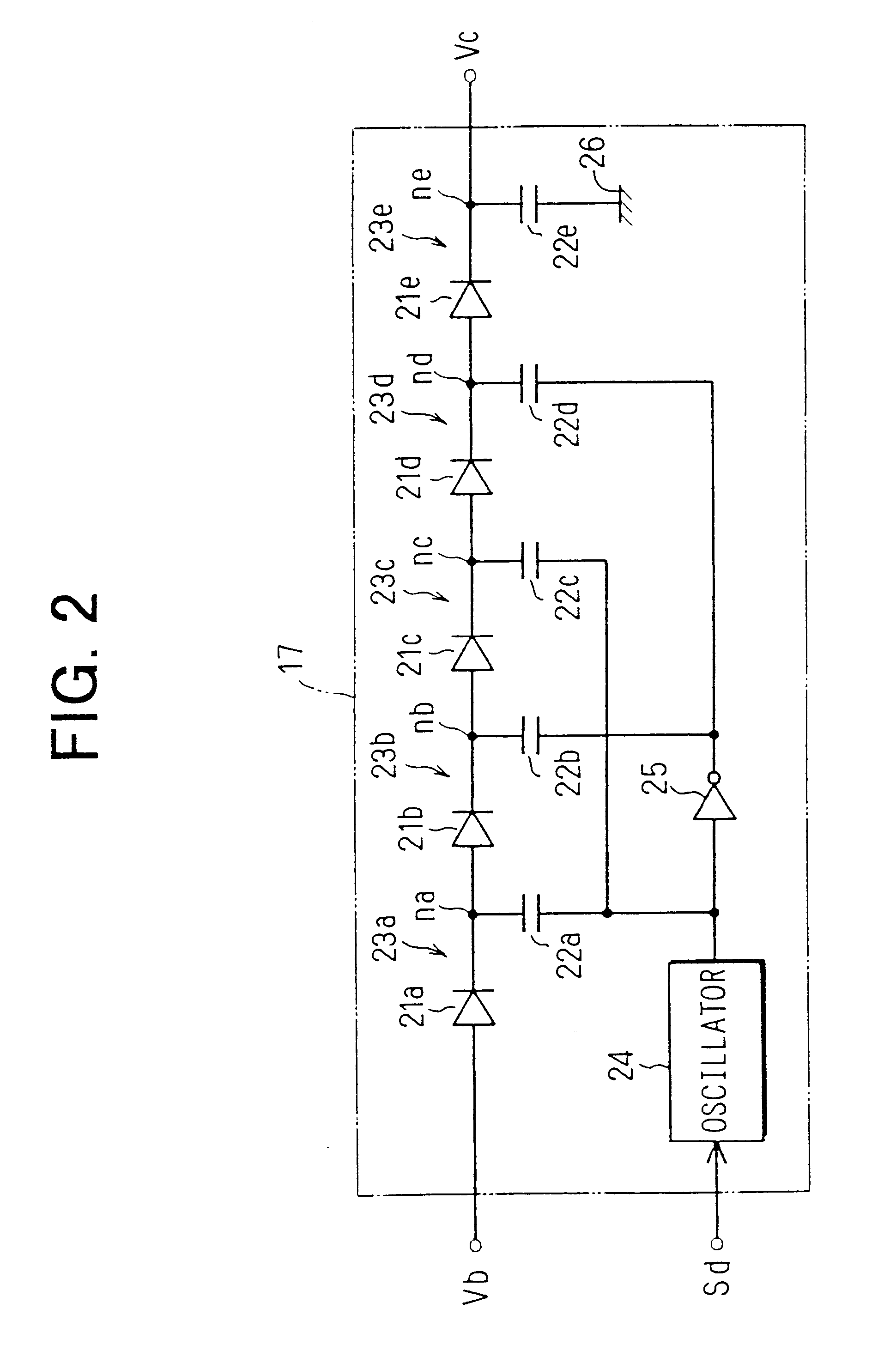
At this time, as explained in the first embodiment, a phenomenon of temporarily jumping down the voltage (battery voltage Vb) of the power line 13 is generated by a sudden increase in a load electric current. The battery voltage Vb becomes a state lower than the threshold value Vh for a time from this time to a time t23 so that the booster circuit 55a stops the voltage raising operation and the raising voltage Vc is therefore reduced. However, the booster circuit 55a accumulates electric charges to its voltage raising capacitors 22a to 22e, and it is prevented by diodes 21a to 21e that the electric charges reversely flow to an input side. Accordingly, the raising voltage Vc is not suddenly reduced, but is gradually reduced.

Further, the threshold value Vh is set to be higher than the threshold value Vd. Accordingly, even when the raising voltage Vc (detecting voltage Va) is reduced, this raising voltage is not immediately reduced until its threshold value Vt (reference voltage Vr). T...

embodiment modes

(Other Embodiment Modes)

The MOSFET 15 is used as a switch circuit (switching element), but an IGBT, a bipolar transistor, or the like may be also used instead of the MOSFET. Further, the switch circuit is not limited to a semiconductor switching element, but a relay switch turned on and off by using e.g., the raising voltage Vc may be also used as the switch circuit.

Power source connected to the power line 13 is not limited to the battery. Further, the charge pump circuit 17 (booster circuit 55a) is not limited to the circuit construction shown in FIG. 2, but another circuit construction may be also used if this circuit is constructed by a diode and a capacitor for preventing the back flow of electric charges. Further, the charge pump circuits 17, 55 may also perform the voltage raising operation at any time irrespective of the voltage level of the drive command signal Sd.

With respect to the series circuit 44 in the low voltage detecting circuits 40, 49, each series connecting numbe...


PUM


Abstract

A charge pump circuit receives a battery voltage of a power line, and outputs a raising voltage proportional to the battery voltage. A low voltage detecting circuit detects a low voltage state in which a detecting voltage obtained by dividing the raising voltage. Thus, it is possible to indirectly detect a low voltage state in which the battery voltage is lower than a predetermined threshold value. When the low voltage state is detected, a drive circuit turns off a MOSFET. At this time, the battery voltage is temporarily varied, but the charge pump circuit has a filter action and a delay action, whereby temporary variation does not easily appear in the raising voltage (detecting voltage), and an error in operation of the MOSFET can be prevented.

Description

This application is based upon Japanese Patent Application No. 2000-187698 filed on Jun. 22, 2000, the contents of which are incorporated herein by reference.1. Field of the InventionThe present invention relates to a load drive circuit having a charge pump circuit for raising a voltage, and a switch circuit for opening and closing a power supply path to a load by using this raised voltage.2. Related ArtFIG. 10 shows the conventional construction of a load drive circuit for driving a load (a relay, a light, etc.) mounted to an automobile. The load drive circuit 1 is constructed by a MOSFET 4 for controlling a conducting state of the load 2, a drive circuit 6 for driving this MOSFET 4, a power circuit 8, a voltage raising (charge pump) circuit 5 for raising and outputting an inputted voltage, and a low voltage detecting circuit 7. The charge pump circuit 5, the drive circuit 6 and the low voltage detecting circuit 7 are activated by receiving the supply of a controlled power voltage ...

Claims


Application Information

Patent Timeline
Patent Type & Authority Patents(United States)
IPC IPC(8): H02M3/07H02M3/04H03K17/30H03K17/22H03K17/06G05F1/10H03K17/687
CPCH02M3/073H03K17/063H03K17/223H03K17/302
Inventor TUCHIYA, NAOYAISHIKAWA, TAKESHIISHIKAWA, FUKUO
Owner DENSO CORP
Why Eureka
Try Eureka