Portable electrical motor driven nail gun

a technology of electrical motors and nail guns, applied in the field of electrical motor driving nail guns, can solve the problems of affecting the performance affecting the accuracy of the nail gun, and requiring a fairly complicated assembly

Inactive Publication Date: 2003-08-12
TRICORD SOLUTIONS
View PDF19 Cites 93 Cited by
  • Summary
  • Abstract
  • Description
  • Claims
  • Application Information

AI Technical Summary

Problems solved by technology

Typical within this design is the need for a fairly complicated assembly.
One of the drawbacks of these types of mechanisms is that the force provided by a solenoid is governed by the number of ampere-turns in the solenoid.
These requirements are counterproductive as the resistance of the coil increases in direct proportion to the length of the wire in the solenoid windings.
This type of design suffers from a second drawback in that the force in a solenoid varies in relation to the distance of the solenoid core from the center of the windings.
This limits most solenoid driven mechanisms to short stroke small load applications such as paper staplers or small brad tackers.
There are several disadvantages in this design that include increased operator fatigue since the actuation technique is a series of blows rather than a continuous drive motion.
A further disadvantage is that this technique requires the use of an energy absorbing mechanism once the nail is seated.
Additionally, the multiple impact designs normally require a very heavy mechanism to insure that the driver does not move during the driving operation.
Several drawbacks exist to this design.
These include the need for a complex system of compressing and controlling the spring and the fact that the force delivery characteristics of a spring are not well suited for driving nails.
The major drawback to this design is the problem of coupling the flywheel to the driving anvil.
This prior art teaches the use of a friction clutching mechanism that is both complicated, heavy and subject to wear.
This design also suffers from difficulty in controlling the energy left over after the nail is driven.
Operator fatigue is also a concern as significant precession forces are present with flywheels that rotate in a continuous manner.
This design is limited by the large precession forces incurred because of the continuously rotating flywheel and the complicated and unreliable nature of the toggle link mechanism.
1. Complexity of design. With the fuel driven mechanisms, portability is achieved but the design is inherently complicated. Mechanisms from the prior art that utilize rotating flywheels have enormously complicated coupling or clutching mechanisms. Devices that use springs as a potential energy storage device also have complicated spring compression mechanisms.
The ignition of an explosive mixture to drive a nail causes a very loud sound and presents combustion fumes in the vicinity of the device.
Multiple impact devices have a loud jack hammer type noise.
3. Complexity of operation.
Combustion driven portable nail guns are more complicated to operate.
The degree of control over the nail operation is very crude as you are trying to control the explosion of a combustible mixture.
6. Using a spring as a potential energy storage device suffers from unoptimized drive characteristics.
Additionally, the unused energy from the spring which is not used in driving the nail must be absorbed by the tool causing excessive wear.
7. The flywheel type storage devices suffer from significant precession forces as the flywheels are not intermittent and are left rotating at high speeds.
This makes tool positioning difficult.
The use of counter-rotating flywheels as a solution to this issue increases the complexity and weight of the tool.
This creates a need for highly complex and precise control over the motor.

Method used


Image

  • Portable electrical motor driven nail gun
  • Portable electrical motor driven nail gun
  • Portable electrical motor driven nail gun

Examples


Embodiment Construction

of the Design

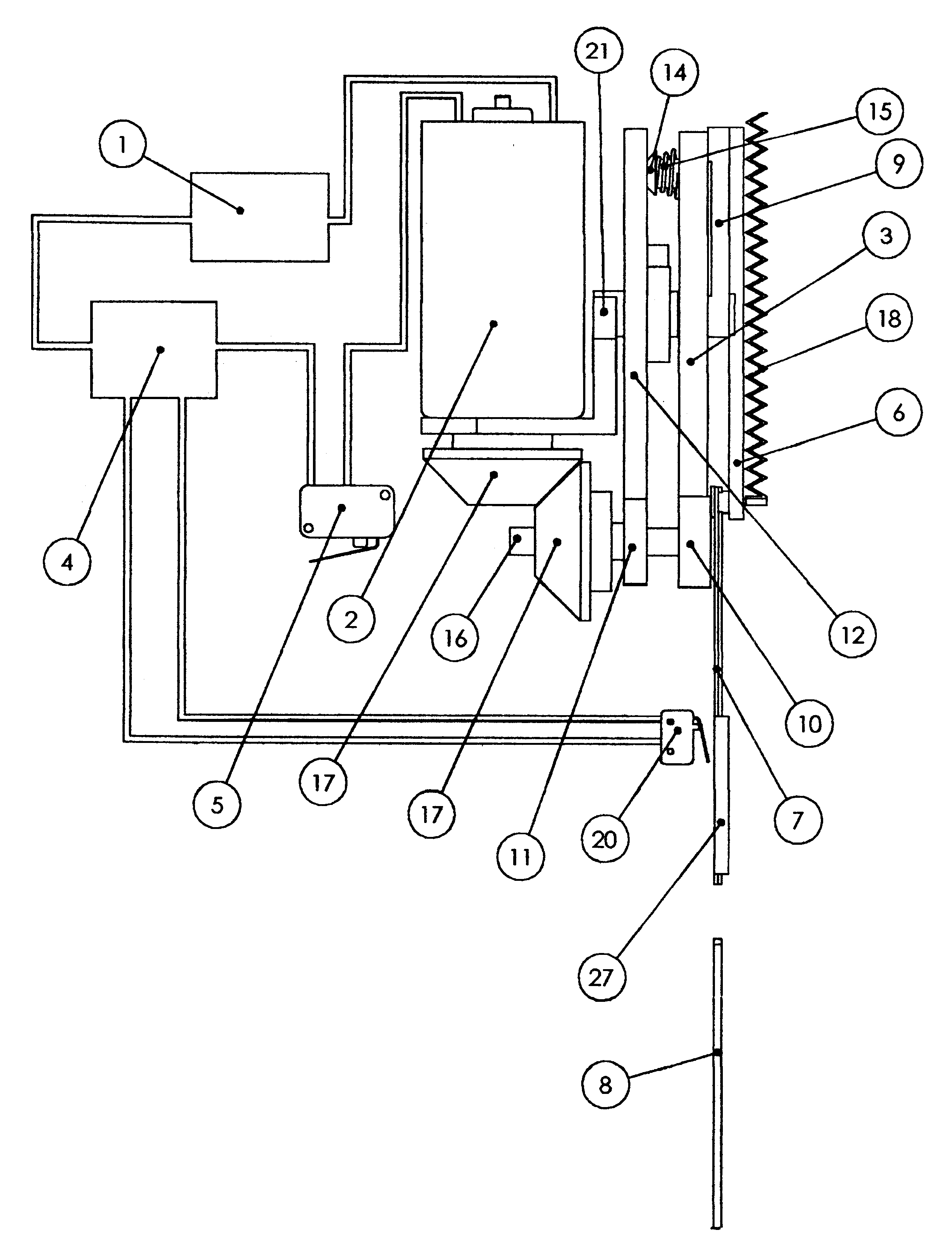
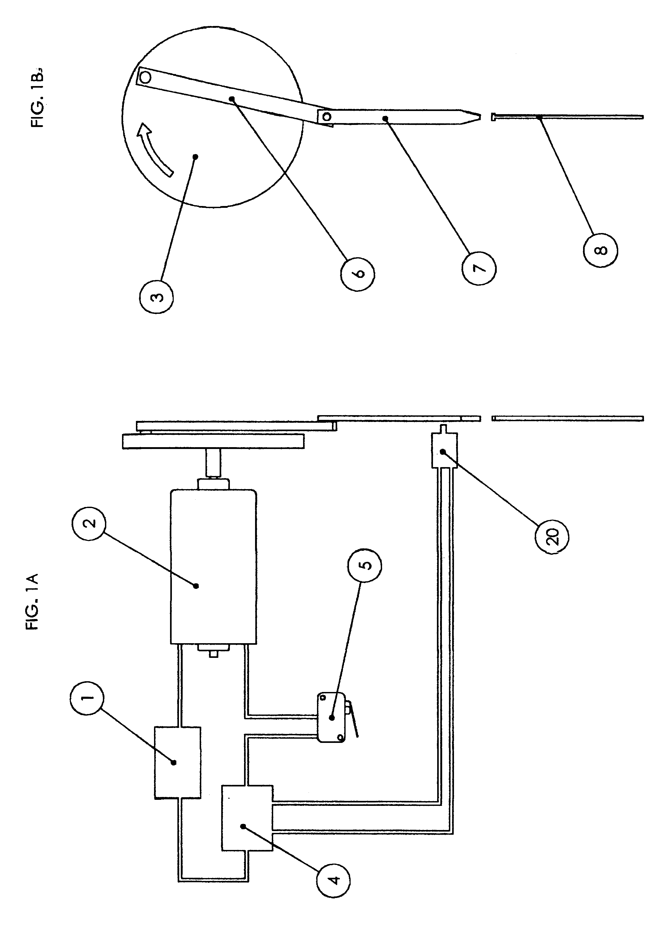
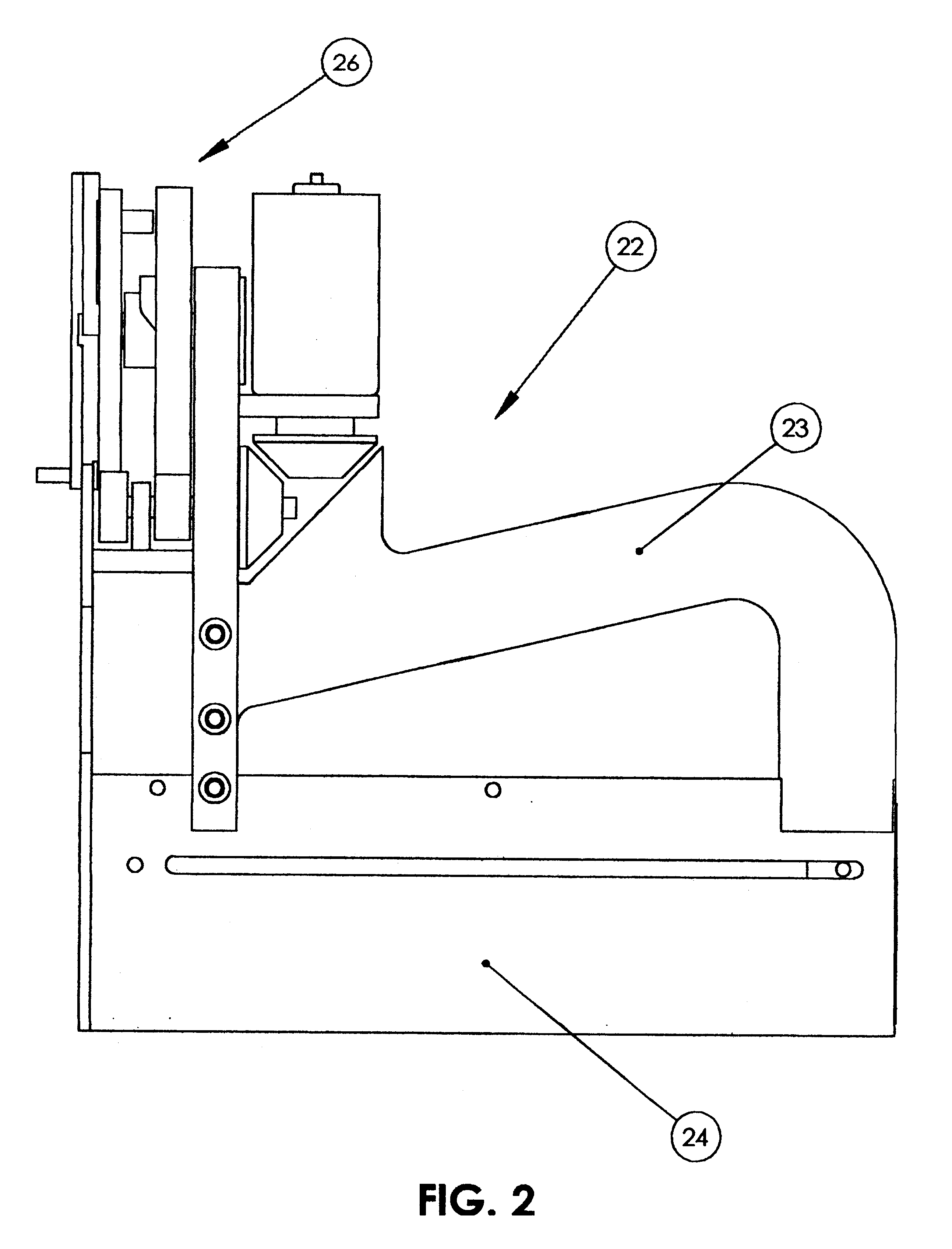
FIGS. 2-5 represent a preferred embodiment of a fastener-driving tool (22) for driving fasteners such as nails (8) into substrates (25) such as wood. Referring to FIG. 2, the preferred embodiment includes a drive unit that can deliver a impact or pulse through a stroke such as, for example, a fastener driving tool (22). The fastener-driving tool (22) comprises a handle (23), a feeder mechanism (24), and the nail driving mechanism (26). The feeder mechanism is spring biased to force fasteners, such as nails or staples, serially one after the other, into position underneath the nail-driving anvil. FIGS. 3-6 detail the nail driving mechanism. Referring to FIG. 3, the motor (2) is controlled over an intermittent cycle to drive a nail (8) beginning by placing the fastener driving tool (22) against the substrates (25) which are to be fastened and actuating a switch (5). This intermittent cycle ends when the nail (8) has been driven and the nail driving mechanism (26) is reset...


PUM

PropertyMeasurementUnit
capacitanceaaaaaaaaaa
cycle timeaaaaaaaaaa
resistanceaaaaaaaaaa

Abstract

A portable electric nailing gun operating from a power supply. The motor accelerates a flywheel which at the appropriate energy state is coupled through a mechanism to an anvil acting directly on the nail. The actuation is governed by a control circuit and initiated from a trigger switch. The motor accelerates a flywheel that is then clutched to the output anvil causing the nail to be driven. The position of the output anvil is sensed and once the nail is driven, the motor is dynamically braked reducing the excess energy in the flywheel. This method uses a highly responsive motor and power supply which enables the motor to come up to speed, drive the nail and return to a low energy condition in less than 2 seconds. The electrical control circuit and brake allow precise control and improve safety. The power supply is preferably a rechargeable low impedance battery.

Description

Not ApplicableREFERENCE TO SEQUENCE LISTING, A TABLE, OR A COMPUTER LISTING COMPACT DISK APPENDIXNot ApplicableBACKGROUND OF INVENTIONThis invention relates to fastening mechanisms, specifically to such nail or staple fastening mechanisms that require operation as a hand tool. This invention relates generally to an electromechanical fastener driving tool. Such devices are less than 15 pounds and are completely suitable for an entirely portable operation.Contractors and homeowners commonly use power-assisted means of driving fasteners into wood. These can be either in the form of finishing nail systems used in baseboards or crown molding in house and household projects, or in the form of common nail systems that are used to make walls or hang sheathing onto same. These systems can be portable (not connected or tethered to an air compressor or wall outlet) or non-portable.The most common fastening system uses a source of compressed air to actuate a cylinder to push a nail into the rec...

Claims


Application Information

Patent Timeline
Patent Type & Authority Patents(United States)
IPC IPC(8): B25C1/00B25C1/06
CPCB25C1/06
Inventor PEDICINI, CHRISTOPHER S.WITZIGREUTER, JOHN D.
Owner TRICORD SOLUTIONS
Why Eureka
Try Eureka