

Seal type storage battery
a storage battery and seal technology, applied in the field of seal type storage batteries, can solve the problems of inability to use repeatedly, overcharge, and the dispersion of the detected delta-v value at overcharge, and achieve the effect of convenient connection
Inactive Publication Date: 2003-08-26
SANYO ELECTRIC CO LTD
View PDF7 Cites 28 Cited by
- Summary
- Abstract
- Description
- Claims
- Application Information
AI Technical Summary
Benefits of technology
Since the seal type storage battery has the pressure-sensitive conductive rubber whose resistance is changed continuously depending on the rise of inner pressure of a battery case so that the detection does not delay because the inner pressure can be immediately output as the detecting signal. In addition, the pressure-sensitive conductive rubber detecting the pressure has superior resistance for transmutation of pressure and temperature so that the structure can prevent its aging. Further, as shown in FIG. 4, the pressure-sensitive conductive rubber has a characteristic that its resistivity changes in accordance with load (pressure) so that it can detect a rise of the inner pressure with accuracy. Especially, the resistitvity is extremely sensitive in the early stage at which load operates, so that the increasing inner pressure can be detected more precisely. Further, the pressure-sensitive conductive rubber shows a superior water-proof quality such that it can effectively prevent the degradation caused by the electrolyte. Accordingly, the seal type storage battery according to the present invention can detect the inner pressure of the battery with accuracy and immediacy using the pressure-sensitive conductive rubber. Thus, overcharging can be prevented for this type of battery over a long period of time with certainty. Furthermore, the seal type storage battery has a lead connected with the pressure-sensitive conductive rubber. The lead is disposed in the battery case and extended to the outside, so that simply connecting the extended lead with the control circuit of the charging circuit can cut the charging current, thus facilitating the connecting work between the seal type storage battery and charging circuit.
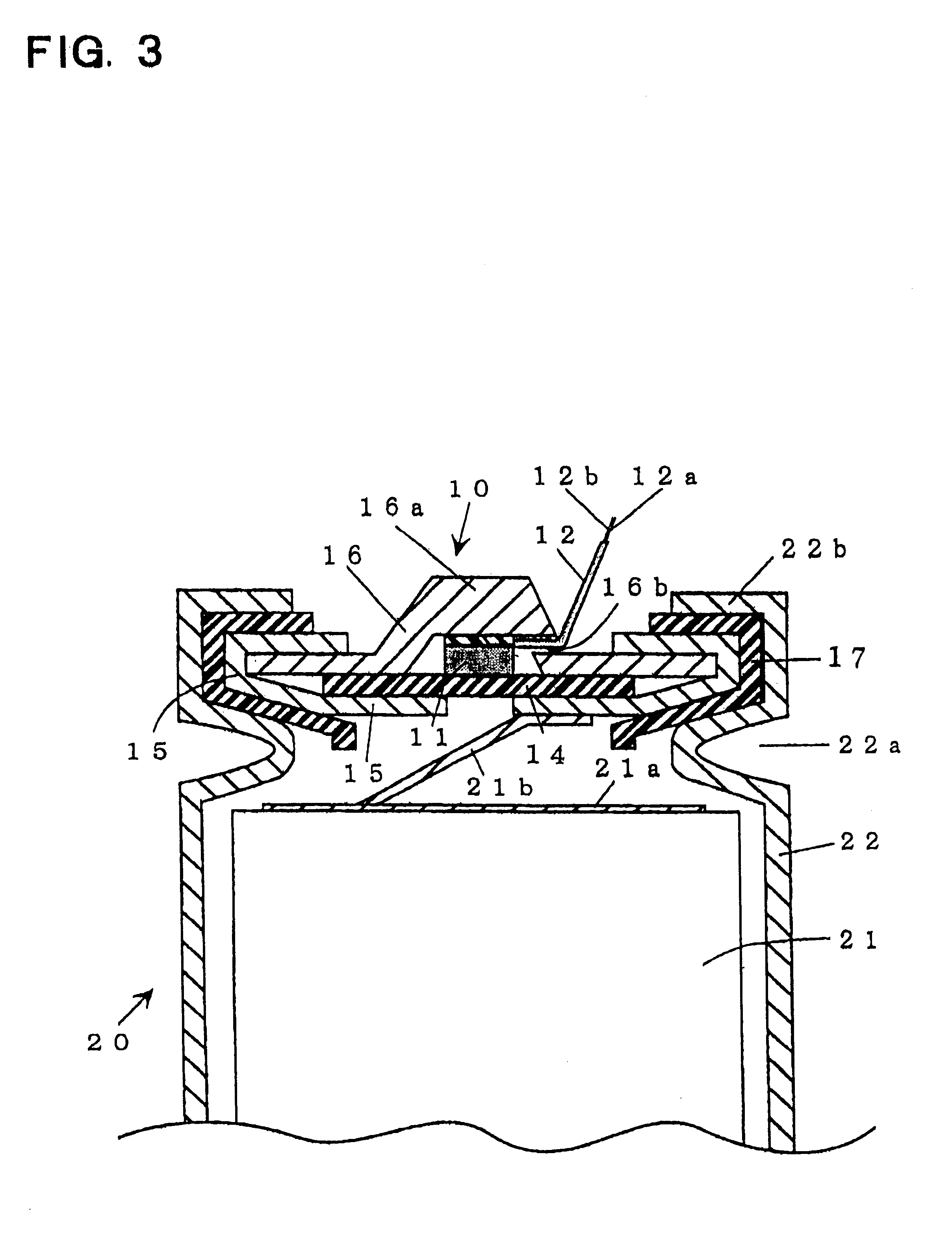
The sealing equipment described above outputs a pressure detecting signal to the charge circuit via the lead extended to outside by detecting a rise of the inner pressure of the battery by the pressure-sensitive conductive rubber disposed inside of the valve. The control circuit of the charge circuit then cuts the charge current to prevent overcharge in the seal type storage battery, when the inner pressure of the battery becomes higher than a predetermined pressure. In addition, the sealing equipment prevents the inner pressure of the battery to become extremely high with the pressure-regulating valve opening the valve, even the control circuit does not cut the charge current in some situations when the inner pressure is higher than the predetermined pressure. Therefore, predetermined pressure with the pressure-regulating valve opening is set higher than the predetermined pressure with the control circuit cutting the charge current.
Problems solved by technology
However the charged voltage depends on charging current or ambient temperature, so that the--delta-V method described above has a problem in that dispersion of the detected delta-V value occurs at overcharge.
On the other hand, the method that controls the charge by detecting the surface temperature of the battery, described above, can detect the difference of the temperature comparatively with accuracy when the charging current is small, but the temperature in short time charging increases quickly so that the method has the problem that an overcharge can occur due to a delay in detecting the increasing temperature.
In this case, it has a problem in that it cannot sufficiently prevent overcharge, since it cannot detect the inner pressure directly so that detection of the inner pressure is delayed, and sensitivity of the detection depends on the condition of the attachment of the strain gauge so that it cannot detect the inner pressure with certainty.
On the other hand, in the method proposed in Japanese Patent Application HEI 5-3644, 1993, it has a problem in that it cannot be used repeatedly when it cuts the charging current directly when charging with a huge amount of charging current, since a detection signal detected by a pressure detector controls a switching device, disposed in a charging circuit, to cut the charging current directly so that the switching device is susceptible to being broken.
In addition, it is difficult to ensure that the pressure detector disposed in the trough will operate stably for a long time, so that it makes it difficult to detect its inner pressure with accuracy to protect the battery effectively.
The detector is disposed under very extreme circumstances such as large variations of pressure or temperature, so that the detector is susceptible to aging.
Further, the detector is exposed to electrolyte, which causes leakage.
Method used
View moreImage
Smart ImageViewing Examples

Examples
example 2
Next, in the batteries A-D, the control circuit, which stops charging in response to the pressure detecting signal detected by the pressure-sensitive conducting rubber, was turned off, and these batteries A-D were charged with the charge current 10 A. It was confirmed that the gas was exhausted by the pressure-regulating valve by opening the valve, when the inner pressure became 1.5 MPa or over 1.5 MPa.
Here, in the embodiments described above, although the present invention is explained to apply to the nickel-cadmium storage batteries, this invention can also apply to a nickel metal hydride seal type storage battery or the like.
Login to View More PUM
| Property | Measurement | Unit |
|---|---|---|
| pressures | aaaaa | aaaaa |
| pressures | aaaaa | aaaaa |
| pressures | aaaaa | aaaaa |
Abstract
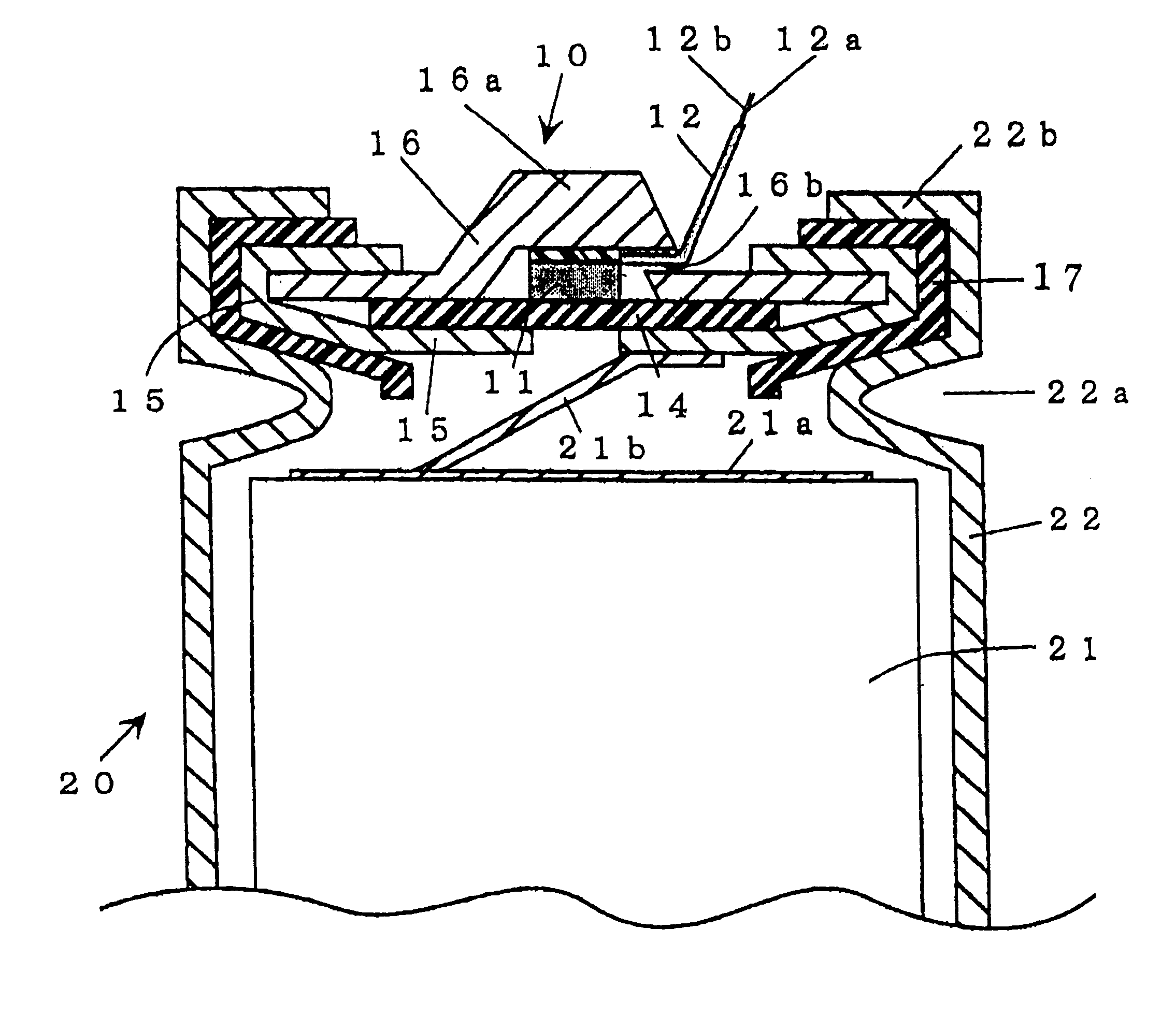
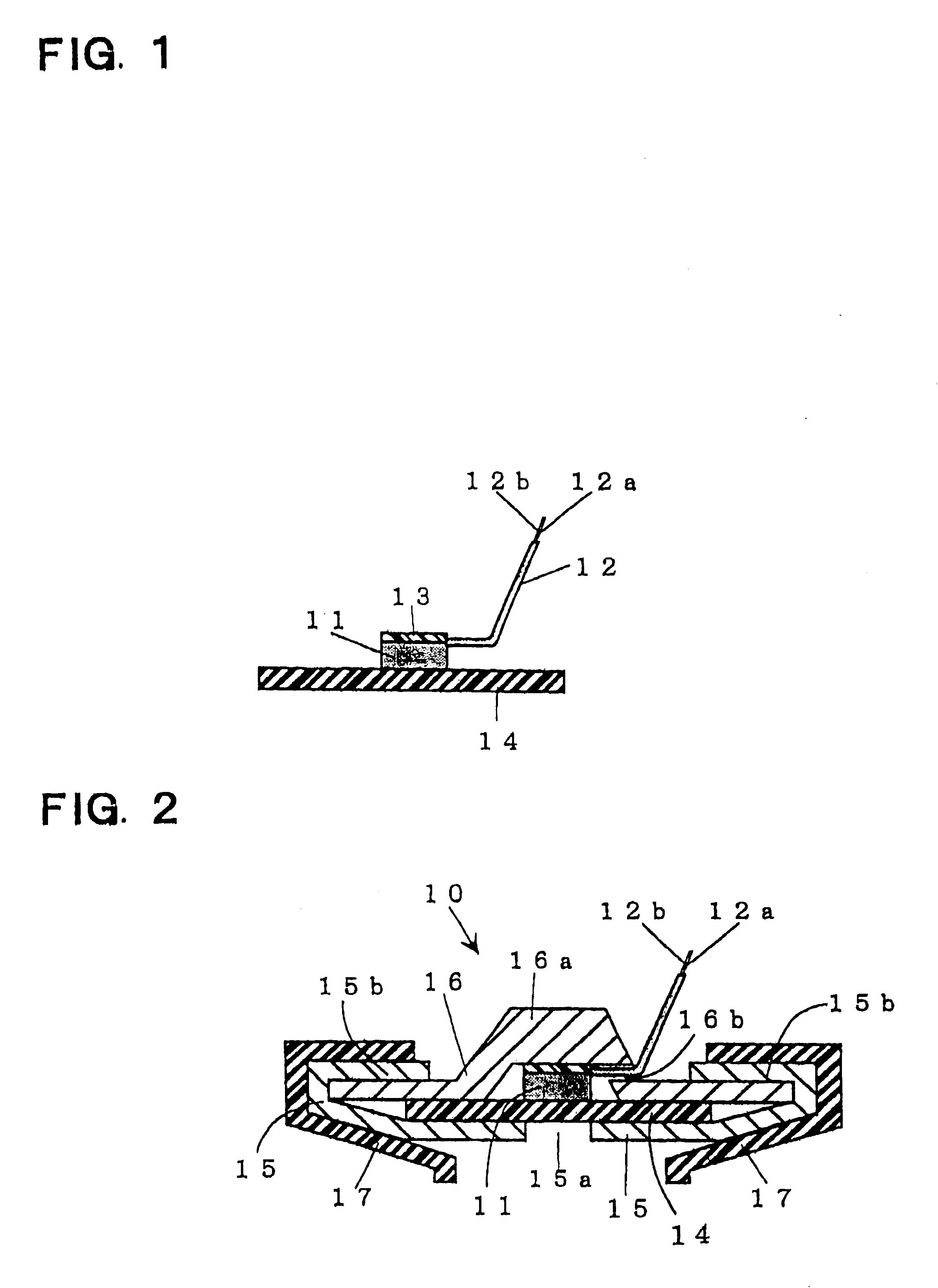
A seal type storage battery has a battery case which has a sealing assembly for sealing an opened portion of an outer case, which holds an electricity generating element. The sealing assembly includes a pressure-sensitive conductive rubber member in the battery case. The pressure-sensitive conductive rubber member has a resistance that changes continuously depending on a rise of inner pressure in the battery case. A lead connecting with the, pressure-sensitive conductive rubber extends outside of the battery case, and the lead is capable of outputting a pressure detecting signal to outside.
Description
This invention relates to a seal type storage battery such as a nickel-cadmium storage battery, a nickel metal hydride type storage battery or the like, in particular, an improve seal type storage battery having a pressure detector for detecting inner pressure of the battery.A seal type storage battery such as a nickel-cadmium seal type storage battery, a nickel metal hydride storage battery or the like produces oxygen gas at a positive electrode when close to charge up, and in some cases hydrogen gas is produced at a negative electrode, thereby increasing the inner pressure of the battery. For this reason, this kind of battery has a relief valve, which exhausts the gas out of the battery when the inner pressure exceeds a predetermined pressure, and the valve closes when the inner pressure is lower than the predetermined pressure.In this case, a decrease of battery capacity occurs due to a decrease of electrolyte in accordance with the process of charge-discharge cycles. Therefore, ...
Claims
Login to View More Application Information
Patent Timeline
 Patent Type & AuthorityPatents(United States)
IPC IPC(8): H01M2/34H01M2/12H01M2/20H01M6/00H01M6/50H01M10/34H01M10/48H01M50/574
CPCH01M2/1229H01M2/34H01M2/345H01M2200/20Y02E60/124Y02E60/10H01M50/325H01M50/578H01M50/574
InventorOKUMURA, NOBUHITONISHIMURA, SATORUTAMAGAWA, TAKUYAKAKIUCHI, HISASHIKATAYAMA, HIROKIINOUE, HIROYUKIFUJISAKA, ETSUYA
OwnerSANYO ELECTRIC CO LTD