Optical time domain reflectometer which measures an optical fiber with different wavelengths according to an order and collectively displays waveform data and a list of events for each waveform in the same screen

a technology of optical fiber and reflectometer, which is applied in the field of optical time domain reflectometer, can solve the problems of affecting the quality of optical fiber, etc., and achieves the effects of facilitating the grasping of optical fiber characteristics, rapid localization of faulty points on the fiber line, and convenient operation

Inactive Publication Date: 2003-08-26
ANRITSU CORP
View PDF8 Cites 80 Cited by
  • Summary
  • Abstract
  • Description
  • Claims
  • Application Information

AI Technical Summary

Benefits of technology

IT is an object of the invention to provide an OTDR that solves the above-mentioned problems and that is easy in operation to facilitate grasping of a difference in characteristics of an optical fiber line caused by a difference in wavelength and also to discriminat...

Problems solved by technology

The above-mentioned prior art OTDR, however, has had to switch the wavelength by the operations of the final controlling element, thus leading to a problem of troublesome operations.
The above-mentioned prior art OTDR has had also to observe the waveform by sequentially switching the waveform data for each wavelength on the final controlling element, thus leading to a problem of difficult...

Method used


Image

  • Optical time domain reflectometer which measures an optical fiber with different wavelengths according to an order and collectively displays waveform data and a list of events for each waveform in the same screen
  • Optical time domain reflectometer which measures an optical fiber with different wavelengths according to an order and collectively displays waveform data and a list of events for each waveform in the same screen
  • Optical time domain reflectometer which measures an optical fiber with different wavelengths according to an order and collectively displays waveform data and a list of events for each waveform in the same screen

Examples


Embodiment Construction

First, the invention is outlined as follows.

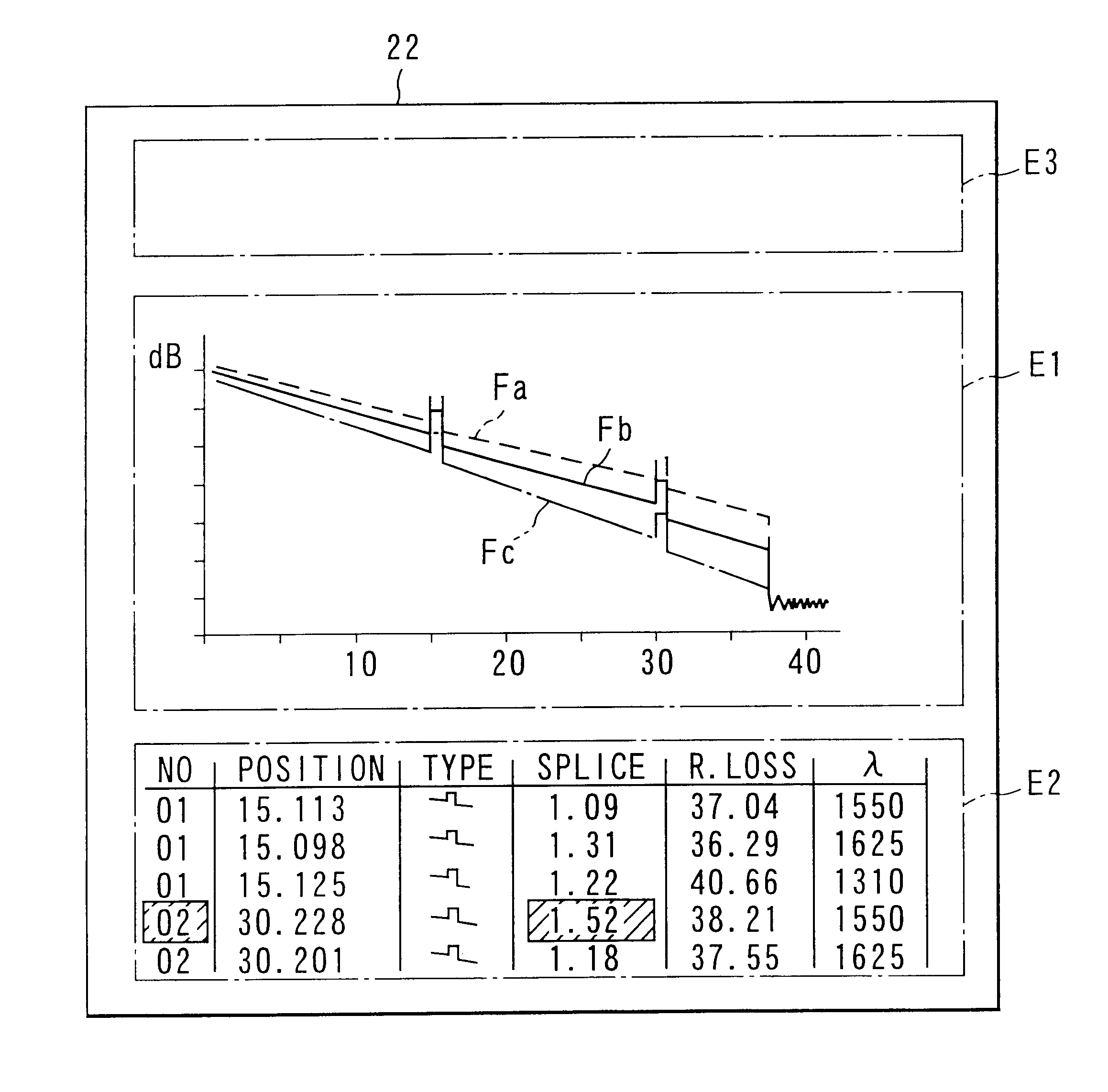
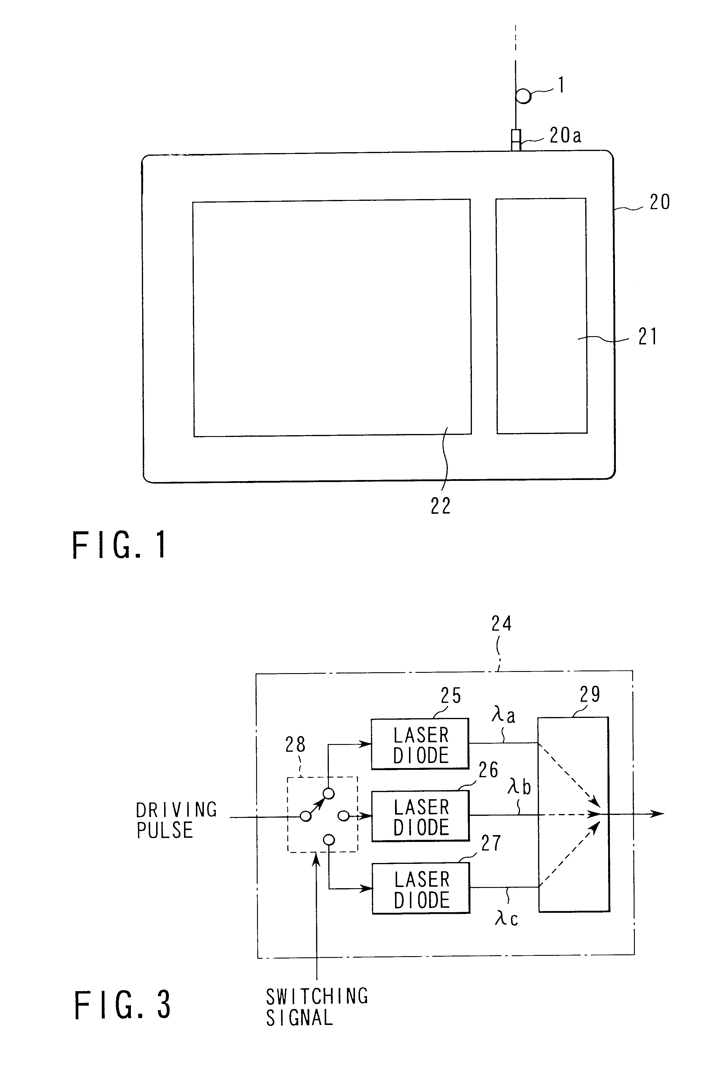
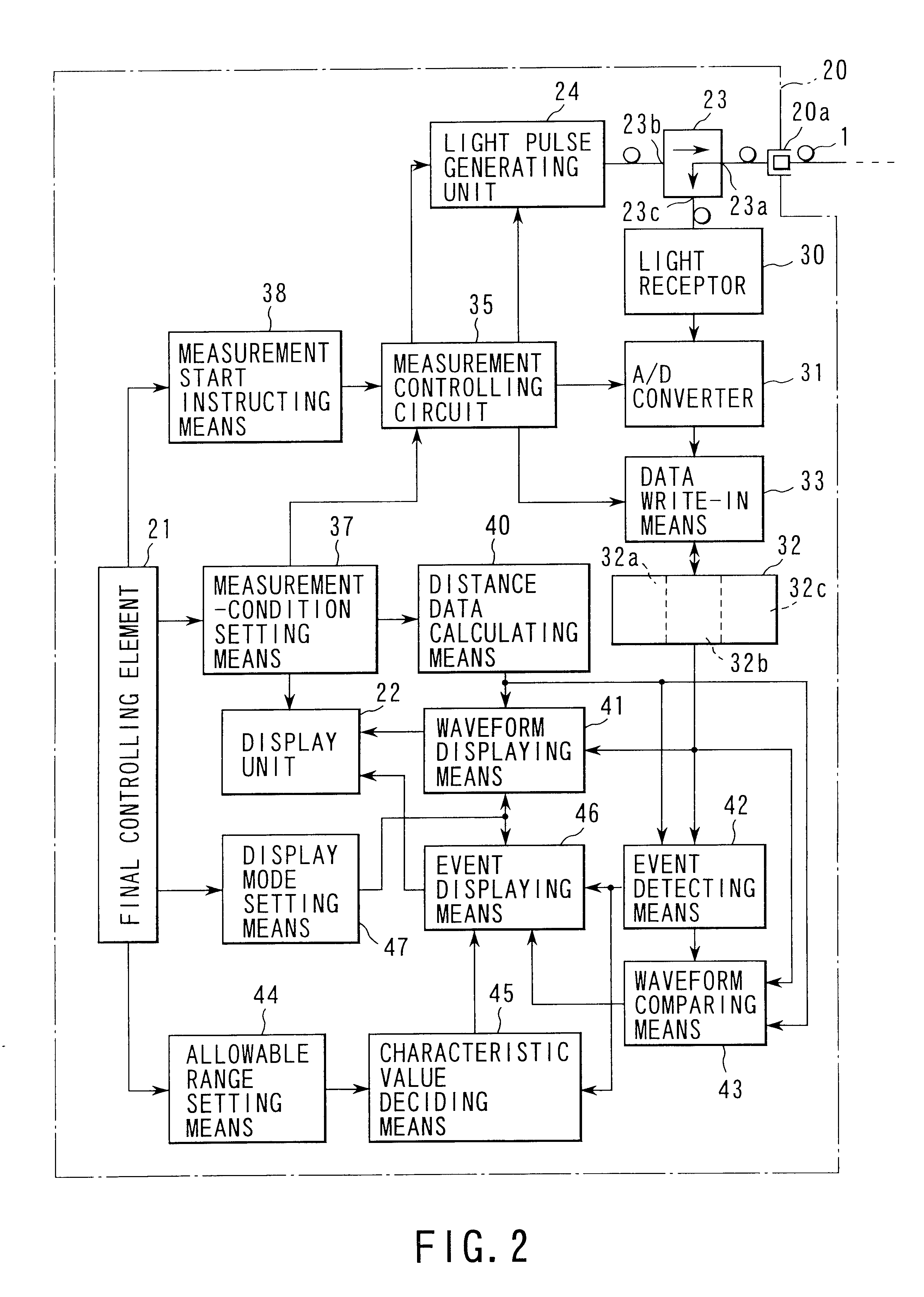
To achieve the above-mentioned object, an OTDR according to the invention comprises a connection terminal (20a) for connecting to one end of an optical fiber line under test, a light pulse generating means (24) formed so as to selectively emit light pulses with different wavelengths for injecting these light pulses via the above-mentioned connection terminal to the above-mentioned one end of the optical fiber, a light receptor (30) for receiving the light injected to the side of the above-mentioned connection terminal from the above-mentioned optical fiber line to then output a reception light signal corresponding to the intensity of that received light, an A / D converter (31) for sampling the reception light signal output from the above-mentioned light receptor to then convert it to a digital value, a memory (32) for storing the data, a data write-in means (33) for storing a series of digital values output from the above-mentioned A / D conv...


PUM


Abstract

A light pulse generator is connected with one end of an optical fiber which selectively emits light pulses of a plurality of wavelengths to the optical fiber. A photodetector outputs a signal corresponding to the strength of the light reflected from the optical fiber. A storage unit stores the signal output from the photodetector for each wavelength. A processor determines the position and characteristic of an event based on the waveform data for each wavelength stored in the storage device. A display device has first and second display areas. A display controller allows the first display area to display the waveform data for each wavelength stored in the storage unit in a discriminable manner, and allows the second display area to display a list of positions and characteristics of events for each wavelength determined by the processor.

Description

This application is a U.S. National Phase Application under 35 USC 371 of International Application PCT / JP00 / 06026(not published in English) filed Sep. 6, 2000.The present invention relates to an optical time domain reflectometer (hereinafter abbreviated to OTDR) and, more particularly to, an OTDR for injecting a light pulse to an optical fiber line under test and then receiving a return light therefrom to thereby measure transmission properties of the optical fiber line, the OTDR employing technologies for facilitating the evaluation of the optical fiber line.An OTDR has conventionally been used to check for a fault or deterioration of an optical fiber line.This type of OTDR injects a light pulse having the same wavelength as that of a light used by a communication system using an optical fiber line to one end of the optical fiber line under test so that until a predetermined time elapses from a time of that injection it can detect the intensity of the light reflected back to that ...

Claims


Application Information

Patent Timeline
IPC IPC(8): G01M11/00G01M11/02
CPCG01M11/3127G01M17/027
Inventor NAKAYAMA, NORIOOSHIMI, TAKASHIHORI, SHIGEOTAMAKOSHI, MASAAKIMIYAKE, YASUHIRO
Owner ANRITSU CORP
Why Eureka
Try Eureka