
Method of making pattern for decorative piece

Inactive Publication Date: 2003-09-09
YANG SHIH SHENG
View PDF26 Cites 10 Cited by
  • Summary
  • Abstract
  • Description
  • Claims
  • Application Information

AI Technical Summary

Benefits of technology

Another objective of the present invention is to provide a method of making patterns for decorative piece, and the decorative piece so formed having a plurality of small conical pins, gives a soft warm touch when it goes with the pulling plate of the zipper, and prevents slippery when force is applied. It thus enhances the visual feeling.

Problems solved by technology

However, the decorative piece of the zipper regardless of its formation by plastic injection of non-metallic materials or by pressing thin metallic plates has patterns or lines with larger size, and even worse its precision cannot be improved.
Furthermore, the texture of the material is hard and cold which gives a feeling of strangeness and lacks the soft warm touch.
Such method forms patterns by traditional plastic injection molding, and thus the patterns so formed have the limitation of fineness and are unable to meet the fineness requirement for the size of only 0.03.about.0.07 mm.
Therefore, general steel mold is not able to produce patterns of such fineness.

Method used


Image

  • Method of making pattern for decorative piece
  • Method of making pattern for decorative piece
  • Method of making pattern for decorative piece

Examples


Embodiment Construction

The following descriptions are of exemplary embodiments only, and are not intended to limit the scope, applicability or configuration of the invention in any way. Rather, the following description provides a convenient illustration for implementing exemplary embodiments of the invention. Various changes to the described embodiments may be made in the function and arrangement of the elements described without departing from the scope of the invention as set forth in the appended claims.

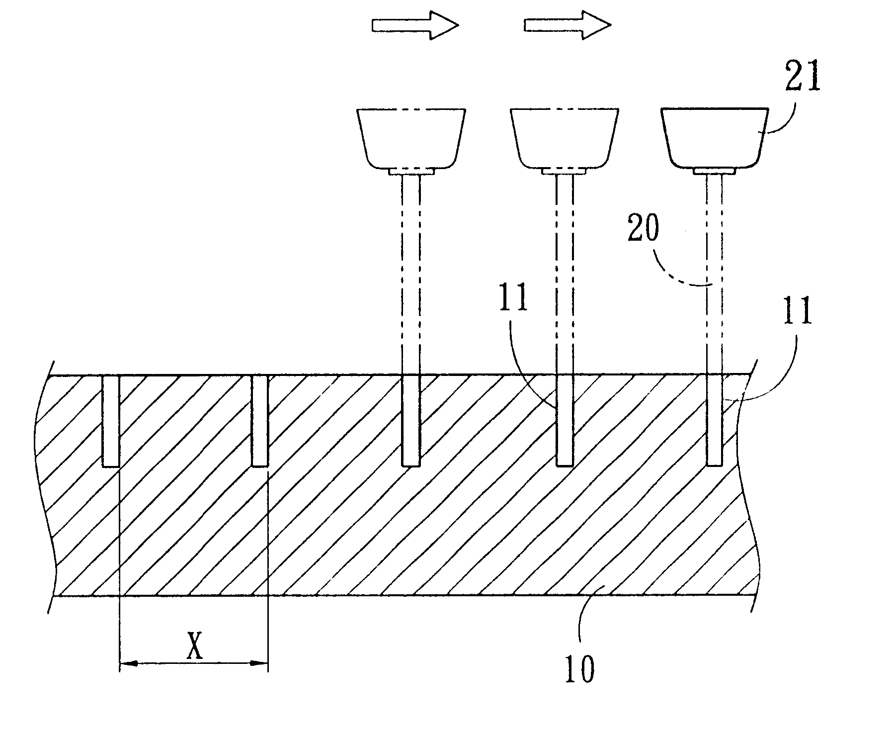
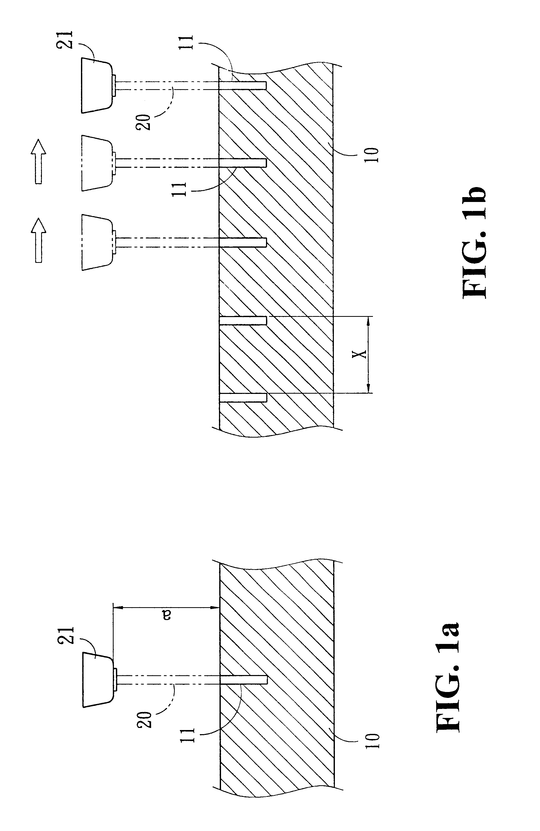
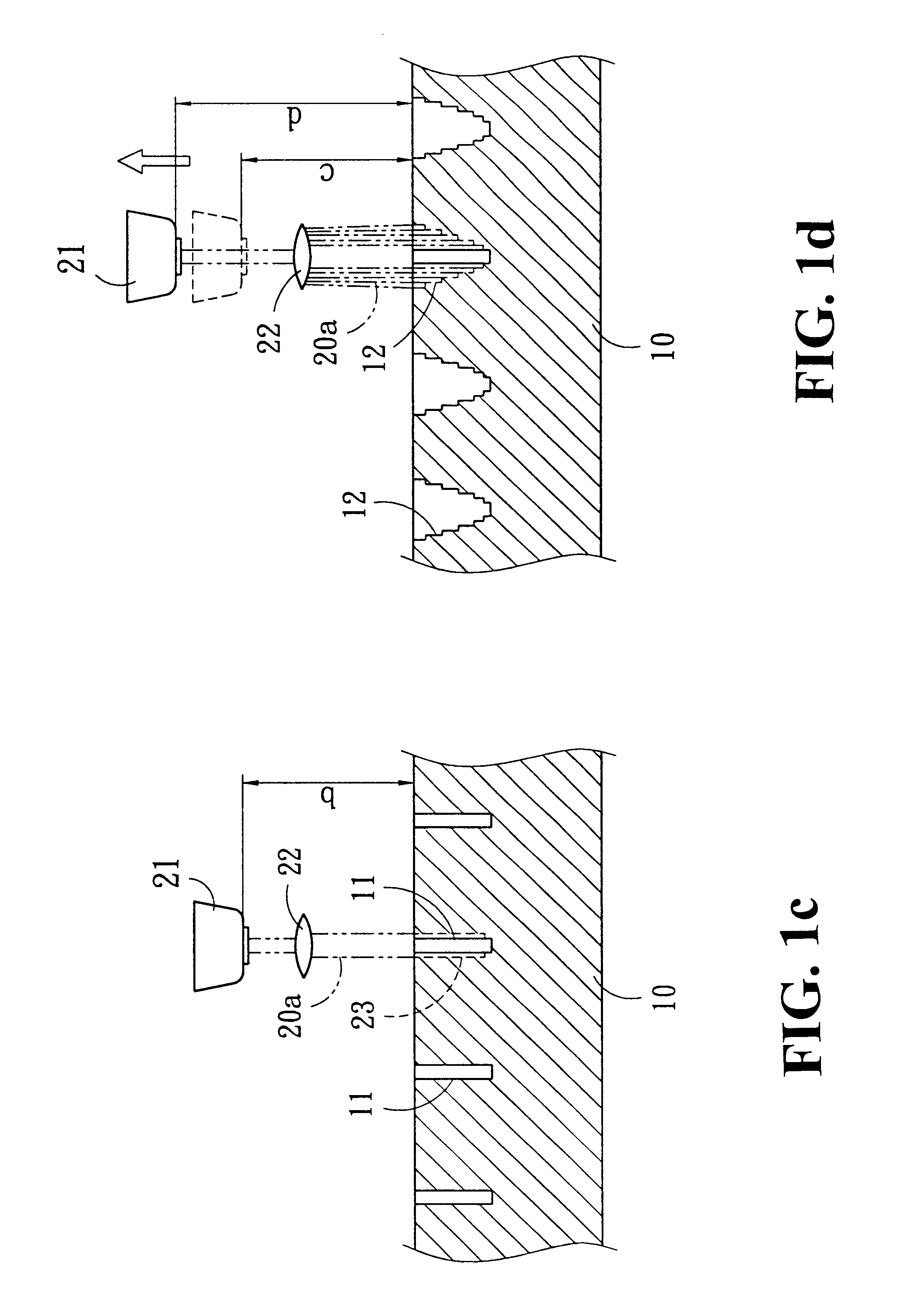
Please refer to FIGS. 1a.about.1d for a preferred embodiment of the present invention, which carves a substrate 10 of a mold by a laser beam 20, and such laser beam 20 is shifted with an increment of x to cut an evenly distributed recession 11 with a specific depth on the a surface first, and then progressively lifts the laser head 2 to a specific height in order to enlarge the diameter of the emitting area of the laser beam 20 by means of the reflection from a convex lens. At that time, the depth cut ...


PUM

PropertyMeasurementUnit
Diameteraaaaaaaaaa
Depthaaaaaaaaaa
Depthaaaaaaaaaa

Abstract

A method of making patterns for decorative piece, comprising the steps of using a metal plate as the molding substrate for laser etching; placing the mold substrate under a laser etching device, and cutting the substrate into a recession of appropriate depth. Further, the height of the laser head of the laser etching device is lifted, and then the dispersion of laser beam can be accomplished by means of a reflective lens. In the meantime, the depth of etching is reduced progressively, and the etching area is expanded along the path of previously cut recession. The manufacturing is made by progressively lifting the laser emitting head according to the theory described above.

Description

BACKGROUND OF THE INVENTION(a) Field of the InventionThe present invention relates to a method of making patterns for decorative piece.(b) Description of the Prior ArtThe conventional decorative piece of a zipper generally adopts the plastic injection method to manufacture all kinds of integral patterns and styles, or pressing thin metallic plates to produce the desired patterns and lines. However, the decorative piece of the zipper regardless of its formation by plastic injection of non-metallic materials or by pressing thin metallic plates has patterns or lines with larger size, and even worse its precision cannot be improved. Furthermore, the texture of the material is hard and cold which gives a feeling of strangeness and lacks the soft warm touch. As disclosed in R.O.C. Patent (Application No. 87113232) entitled "Method of making multi-color decorative piece for zipper head", it shows a method of making a decorative piece fro zipper by plastic injection method. Such method form...

Claims


Application Information

Patent Timeline
IPC IPC(8): A44B19/26A44B19/24B23K26/38B23K26/00B44C1/22
CPCA44B19/262B23K26/383B23K26/385B44C1/228B23K26/384B23K26/389
Inventor YANG, SHIH-SHENG
Owner YANG SHIH SHENG
Learn More