Ignition system

a technology of ignition system and ground electrode, which is applied in the direction of spark plugs, electric devices, machines/engines, etc., can solve the problems of large amount of ground electrode projection, and difficult application of parallel electrode type spark plugs to such internal combustion engines

Inactive Publication Date: 2003-09-09
NGK SPARK PLUG CO LTD
View PDF27 Cites 13 Cited by
  • Summary
  • Abstract
  • Description
  • Claims
  • Application Information

AI Technical Summary

Benefits of technology

With this design, more of the spark jumps that are created by application of high voltage occur anywhere but along the surface of the porcelain insulator. In particular, according to an experiment on spark plugs that were operated with positive high voltage being applied to the central electrode, an appreciably increased proportion of the spark jumps occurred at the tip of the central electrode which was distant from the surface of the porcelain insulator. This enabled the spark plugs to be fired efficiently. What is more, the proportion of spark jumps along the surface of the porcelain insulator decreased dramatically during normal service and the chance of the spark of damaging the surface of the porcelain insulator is correspondingly reduced to make the spark plugs more resistant to channeling.

Problems solved by technology

On the other hand, the internal combustion engine having high power and high performance, particularly the internal combustion engine for a motor cycle, has problems of breakage of the ground electrode due to mechanical vibration and excess heat of the ground electrode.
It is difficult to apply the parallel electrode type spark plug to such an internal combustion engine.
Consequently, the large amount of projection of the ground electrode like the parallel electrode type spark plug is difficult.
In the multi-electrode type spark plug, if the ignition system in the negative polarity, it becomes a serious problem that the wearing of the central electrode which is collided with positive ions having heavy mass.
Further, since a problem of a carbon fouling during low load may easily occur, a semi-creep discharge type or an intermittent semi-creep discharge type of spark plugs have been used, in which a plurality of ground electrodes are provided to oppose to the peripheral side of the central electrode, and spark runs on the surface of the porcelain insulator between the central electrode and the ground electrode.
Accordingly, the channeling problem on the surface of the porcelain insulator easily occur.
If the channeling proceeds, the heat resistance and the reliability of the spark plug are lowered to thereby shorten the life of the spark plug.
However, particularly, if the diameter of the central electrode of the spark plug is small which is used for the negative ignition system, the electrode is rapidly worn and the ground electrode is partially worn.
Accordingly, the life of the spark plug is shortened and it can not be used for practical use.
As a result, spark is more prone to be attracted toward the surface of the porcelain insulator 1, increasing the chance of the occurrence of channeling.
Incidentally, if the central electrode is made too thin, it is excessively heated because of break of the balance between receiving heat and discharging heat.

Method used


Image

  • Ignition system
  • Ignition system
  • Ignition system

Examples


first embodiment

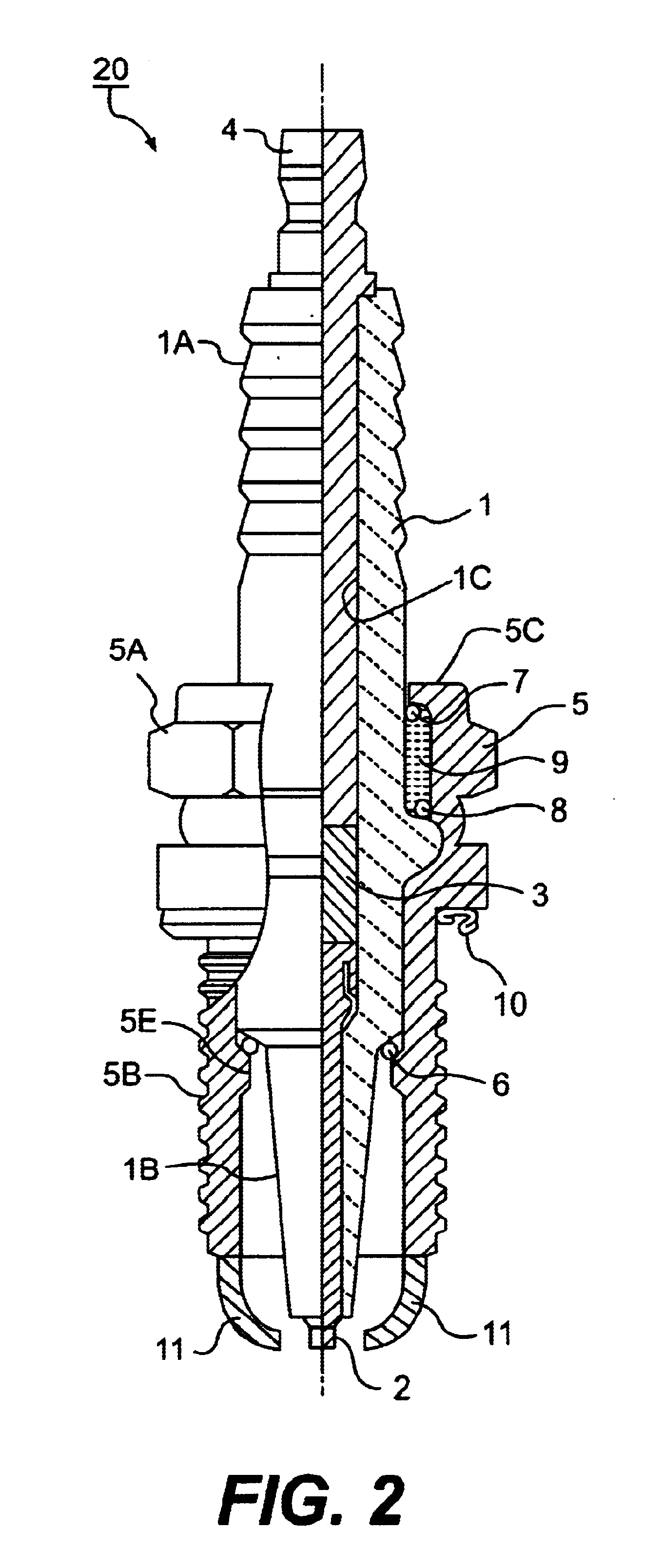
FIG. 3 is a sectional view showing enlarged the distal end portion of a spark plug used in the ignition system according to the invention. The tip of the spark plug shown at the bottom of FIG. 2 is inverted in FIG. 3 and 15 shown at the top. That part of the central electrode 2 which is just above the porcelain insulator 1 is tapered so that its distal end portion has a smaller diameter. The entire part of the central electrode 2 that lies above the porcelain insulator 1 is not reduced in diameter but instead the base is thicker than the distal end portion; this is in order to ensure that the heat generated on the central electrode 2 is effectively dissipated to prevent its distal end portion from becoming overheated. A spark wear resistant member 21 in platinum (Pt) is laser welded to the peripheral side of the smaller-diameter, distal end portion of the central electrode 2. The two ground electrodes 11 are positioned diametrically to each other and project from the end face of the...

second embodiment

FIG. 8 is a sectional view showing enlarged the distal end portion of a spark plug used in the ignition system according to the invention. The two ground electrodes 11 made of 95% of Ni are positioned diametrically to each other and the mating surface 11A of each ground electrode 11 is opposed to the peripheral side of the central electrode 2. Each ground electrode 11 is disposed such that the rear edge of the end face 11A (downward in FIG. 8) is disposed in the side of the distal end (upward in FIG. 8) in comparison with the end face of the porcelain insulator 1. In addition, the shortest distance L from the end face 11A of the ground electrode 11 to the porcelain insulator 1 is adjusted to be smaller than the shortest distance a from the end face h A of the ground electrode 11 to the peripheral side of the central electrode 2.

Details about the dimensions of the distal end parts of the spark plug are given below. The central electrode 2 has diameter A which takes the value 2.0 (in ...


PUM


Abstract

An ignition system has a spark plug and a positive voltage applying unit. The spark plug includes a central electrode, a porcelain insulator for holding the central electrode, a main metallic shell for holding the porcelain insulator, and a ground electrode electrically connected to the main metallic shell. The positive voltage applying unit applies a positive voltage to the central electrode of the spark plug in comparison with the ground electrode, so that an ignition high voltage is applied between the central electrode and the ground electrode. In the spark plug, a spark discharge gap is formed between the ground electrode and a distal end portion of the central electrode. The ground electrode is positioned so that a rear edge of a mating face opposed to a peripheral side of the central electrode is positioned in the side of the distal end of the central electrode in comparison with an end face of the porcelain insulator.

Description

1. Field of the InventionThe present invention relates to an ignition system used for an igniter of an internal combustion engines, and particularly relates to an ignition system using a spark plug that can be effectively spark cleaned to have high resistance to fouling.2. Description of the Related ArtIn a parallel electrode type spark plug in which the distal end face of a central electrode opposes to a ground electrode, the voltage required is lower at the negative polarity than at the positive polarity and, hence, this type of spark plugs have been commonly used with an ignition system of negative polarity that applies a negative, high voltage to the central electrode. Accordingly, even in a semi-creep discharge type or an intermittent semi-creep discharge type of spark plugs that have a plurality of side ground electrodes provided to face the peripheral side of the central electrode, they are often used with the ignition system of negative polarity.On the other hand, the intern...

Claims


Application Information

Patent Timeline
Patent Type & Authority Patents(United States)
IPC IPC(8): H01T13/39H01T13/46H01T13/00
CPCH01T13/39H01T13/467
Inventor MATSUBARA, YOSHIHIROKOKUBU, AKIOYOSHIDA, KAZUMASAYAMAGUCHI, MAKOTOIWATA, KAZUYAITO, SHOICHIROONO, HIROSHI
Owner NGK SPARK PLUG CO LTD
Why Eureka
Try Eureka