Digital camera and printing system

a digital camera and printing system technology, applied in the field of digital cameras, can solve the problems of difficult installation of software, difficult to understand how to enter commands, and take a long time to star

Inactive Publication Date: 2003-09-09
SEIKO EPSON CORP
View PDF21 Cites 201 Cited by
  • Summary
  • Abstract
  • Description
  • Claims
  • Application Information

AI Technical Summary

Problems solved by technology

However, it takes time (so-called overhead time) to enter commands and read the print processing application program and the printer driver; the overhead time requires several minutes at the shortest, thus it takes time to start.
Although PCs are finding remarkable spreading use, many problems remain to be solved for users to know how to actually handle PCs; it is also pointed out that

Method used


Image

  • Digital camera and printing system
  • Digital camera and printing system
  • Digital camera and printing system

Examples


first embodiment

FIG. 8 is a flowchart to show an operation example of image selection means 45A. In the operation example, photographed image data pieces are displayed in order on a liquid crystal display and the user is requested to select a desired print image and specify print specifications of the number of print sheets, print paper size, print color mode (color, single color, or monochrome), etc., then print image data is prepared and transmitted to an external system.

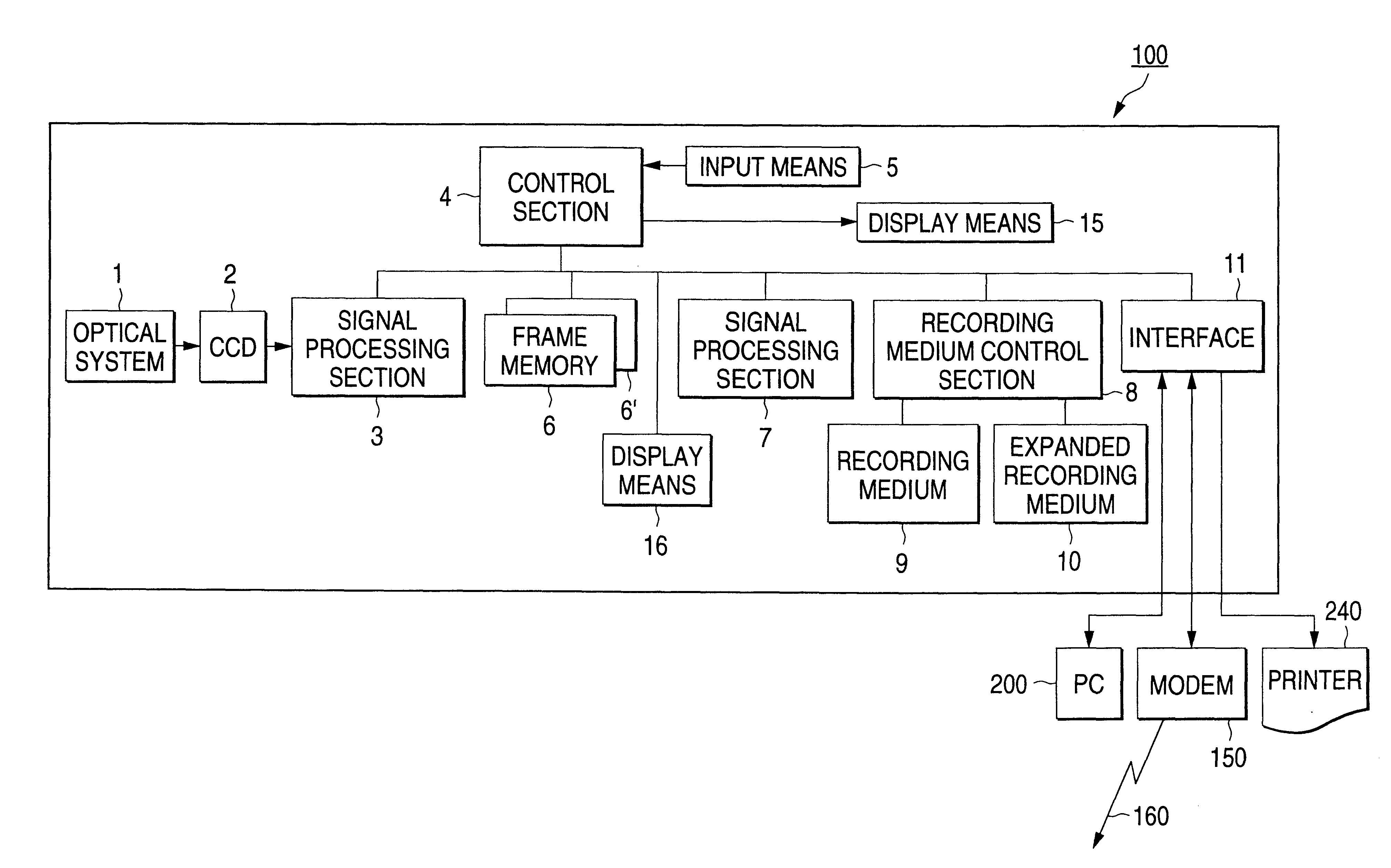
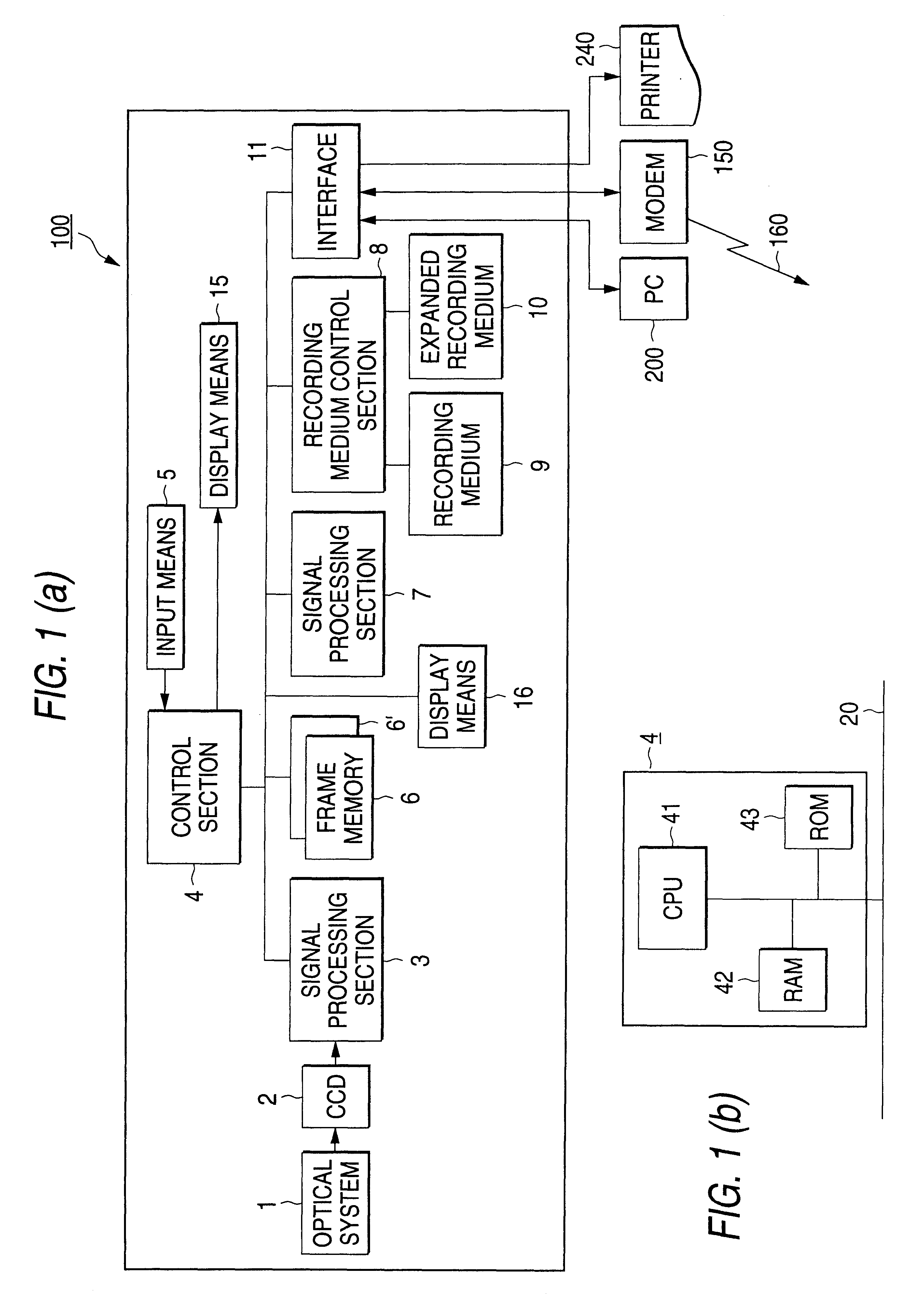
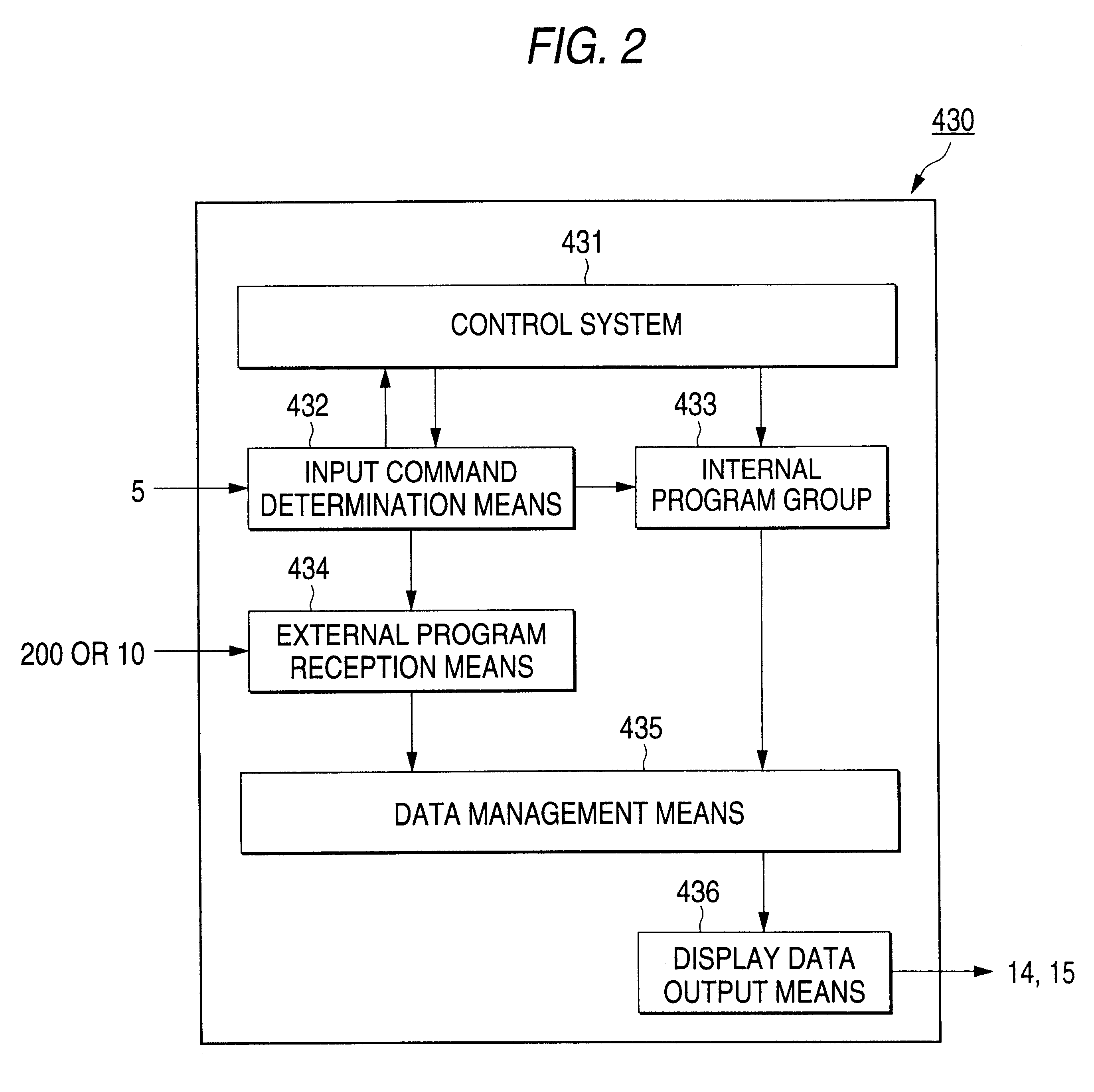
When the image selection means 45A is transferred to a RAM 42, a control system 431 transfers control to the image selection means 45A. Print image selection means 453 reads 1-frame image data, transfers the image data to a frame memory 6, uses a data decompression program to decompose JPEG image data, and displays a candidate image 31 on a liquid crystal display 16 at step S1. In this case, an index number is added to the candidate image on the display.

If the user continues to press a button 19, the print image selection means 4...

second embodiment

FIG. 9 is a flowchart to show an operation example of image selection means 45B (FIG. 3B) wherein thumbnail images are displayed and the user selects a desired image and specifies print specifications of the number of print sheets, print paper size, print color mode, etc., and an output unit to which image data is to be transmitted.

When the image selection means 45B is transferred to a RAM 42, a control system 431 transfers control to the image selection means 45B. Thumbnail image display means 452 reads all thumbnail image data and expands the data in the RAM 42 at step S21.

The thumbnail image display means 452 uses a data decompression program to decompose the thumbnail image data, enlarges the image data, adds an index number to the enlarged thumbnail image data, and displays the thumbnail image on a liquid crystal display 16 at step S22. A number of thumbnail images may be displayed on the liquid crystal display 16 without enlarging the thumbnail image data.

Each time the user pr...

third embodiment

FIG. 10 is a flowchart to show an operation example of image selection means 45C (FIG. 3c) wherein thumbnail image data is printed at a printer and the user selects a desired image from among the printed thumbnail images and specifies print specifications of the number of print sheets, print paper size, print color mode, etc., and an output unit to which image data is to be transmitted.

A control system 431 expands programs contained in a print image data preparation program group 50 in a RAM 42 in order and transfers control to the image selection means 45C at step S31.

Thumbnail image print means 452' reads all thumbnail image data, expands the image data in the RAM 42, decompresses the thumbnail image data in the RAM 42, and adds an index number to each thumbnail image data piece at step S32.

As described at steps S12 to S15 in FIG. 8, the print image data preparation program group 50 performs RGB conversion processing, rasterize processing, color correction processing, and halftone...


PUM


Abstract

With a digital camera 100, a photographed image 31 is displayed on a liquid crystal display and the user selects a desired image and specifies print specifications of the number of print sheets, a print paper size, a print color mode, etc., then print image data is prepared. The prepared print image, data is transmitted from the digital camera 100 to a color printer of an output unit. An image is printed at the color printer in accordance with the print image data.

Description

1. Field of the InventionThis invention relates to a digital camera and in particular to a digital camera capable of outputting image data directly to a printer and a printing system using the same.2. Related ArtIn recent years, digital cameras (still-video cameras) have been developed, sold, and finding spreading use.The digital camera is configured to execute photoelectric conversion of image pickup light to provide image data, record the image data on a recording medium, and output the recorded image data to an external image processing system such as a personal computer (PC). The external image processing system performs print image data preparation processing and outputs the prepared print image data to a printer for printing or reproducing the picked-up image on paper.Most digital cameras comprise each a liquid crystal display for displaying the image pickup result and the image data provided by photoelectric conversion is compressed and recorded on a recording medium. To comp...

Claims


Application Information

Patent Timeline
IPC IPC(8): H04N1/21H04N1/00G06F3/12G06T9/00H04N5/225H04N5/76H04N5/91
CPCG06T9/007H04N1/00127H04N1/00132H04N1/00172H04N1/00188H04N1/00278H04N1/00957H04N1/00962H04N1/2112H04N5/772H04N9/04H04N1/00204H04N5/765H04N5/907H04N9/8047H04N9/8205H04N9/8227H04N2101/00H04N2201/0013H04N2201/0068H04N2201/0082H04N2201/0084H04N2201/0093H04N2201/3216H04N2201/3222H04N2201/3226H04N2201/3242H04N2201/33378H04N23/10
Inventor SHIOHARA, RYUICHI
Owner SEIKO EPSON CORP
Why Eureka
Try Eureka