Organic light-emitting device

a light-emitting device and micro-optical resonator technology, which is applied in the direction of discharge tube luminescnet screens, active medium materials, natural mineral layered products, etc., can solve the problems of poor light-emitting characteristics of organic light-emitting devices comprising electrodes, remarkable light loss, and poor light-emitting characteristics

Inactive Publication Date: 2003-09-16
UDC IRELAND
View PDF5 Cites 27 Cited by
  • Summary
  • Abstract
  • Description
  • Claims
  • Application Information

AI Technical Summary

Problems solved by technology

Organic light-emitting devices generally act as a light source that perfectly diffuses light, thereby suffering remarkable loss in light quantity when they are used for liquid crystal projectors, optical communication devices, light-exposing devices of printers, etc.
However, when the thickness of the electrode is reduced, surface resistance of the electrode is unavoidably increased, whereby the organic light-emitting device comprising the electrode is poor in light-emitting characteristics, durability, etc.
Further, though Japanese Patent Laid-Open No. 11-288786 disclosed a micro-optical resonator type organic light-emitting device having optical length that is increased to lower surface resistance of ITO electrode, this device is disadvantageous in that multi mode resonance is often obtained.

Method used


Image

  • Organic light-emitting device
  • Organic light-emitting device
  • Organic light-emitting device

Examples


Embodiment Construction

The micro-optical resonator type organic light-emitting device of the present invention will be explained in further detail by the following examples without intention of restricting the scope of the present invention defined by the claims attached hereto.

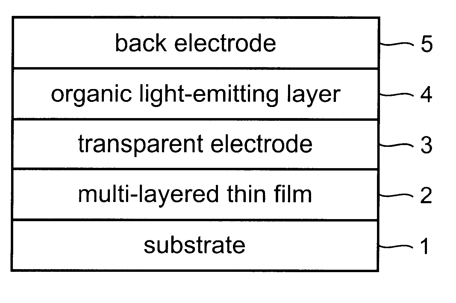
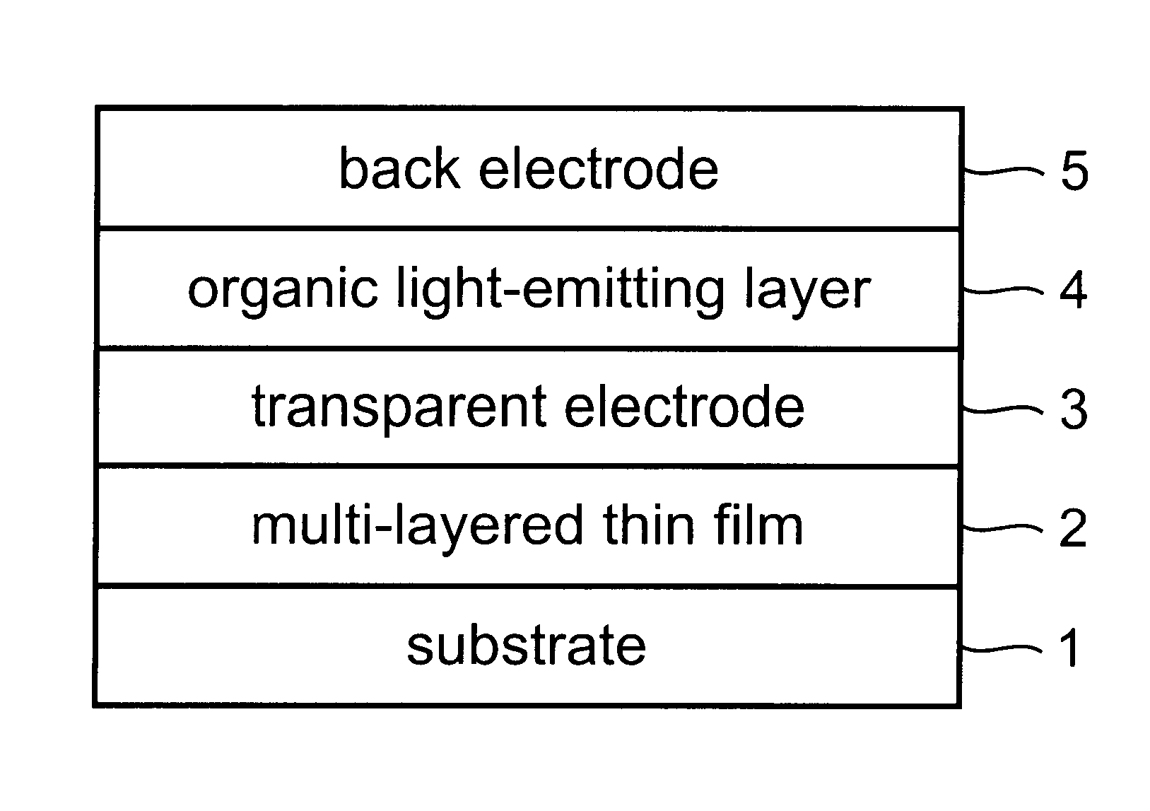
1. Preparation of Laminate Composed of Substrate and Multi-Layered Thin Film

A glass substrate of 5.0 cm.times.5.0 cm in size was washed with ultrasonic wave in a mixture of acetone, Semico Clean (Furuuchi Kagaku Co.) and isopropyl alcohol (PA). The substrate was further washed by boiling in IPA and treated with UV / O.sub.3 washing. This washed substrate was then placed in an EB metallizing chamber, and a multi-layered thin film, which has the reflectivity of 60% against each light in the wavelength range 1 (530 to 550 nm), the wavelength range 2 (590 to 640 nm) and the wavelength range 3 (660 to 780 nm), was disposed thereon, to obtain the comparative laminate A composed of the substrate and the multi-layered thin film.

The above ste...


PUM

PropertyMeasurementUnit
reflectivityaaaaaaaaaa
thicknessaaaaaaaaaa

Abstract

A micro-optical resonator type organic light-emitting device comprising a substrate, and a multi-layered thin film, a transparent electrode, an organic light-emitting layer and a back electrode disposed on the substrate. If 0-mode resonance wavelength of the organic light-emitting device is expressed by lambd0, n-mode resonance wavelength of the organic light-emitting device is expressed by lambdn (in which n is a positive integer) and reflectivity of the multi-layered thin film against light having a wavelength lambd is expressed by R(lambd), R(lambd0) is 40% or more and R(lambd1) or R(lambd2) is 30% or less.

Description

The present invention relates to an organic light-emitting device.Organic light-emitting devices generally act as a light source that perfectly diffuses light, thereby suffering remarkable loss in light quantity when they are used for liquid crystal projectors, optical communication devices, light-exposing devices of printers, etc. It is thus desired to develop an organic light-emitting device excellent in light emission directivity, and some proposals have been made therefor. For example, Japanese Patent Laid-Open No. 9-180883 disclosed a micro-optical resonator type organic light-emitting device, which controls emitting quantity of light other than those in directions perpendicular to a substrate to a low level, thereby exhibiting excellent light emission directivity. This micro-optical resonator type organic light-emitting device has a micro-optical resonator provided by disposing an organic layer between a conductive multi-layered mirror and a metal mirror, and has a resonance w...

Claims


Application Information

Patent Timeline
Patent Type & Authority Patents(United States)
IPC IPC(8): H01L51/50H01L51/52H05B33/12H05B33/14H05B33/22
CPCH01L51/5265Y10S428/917H10K50/852
Inventor ARAKI, YASUSHI
Owner UDC IRELAND
Why Eureka
Try Eureka