Array type microresonant cavity tunable integrated optical filter

An optical filter and micro-resonator technology, applied in the field of optical filters, can solve the problems of high cost, inefficiency, difficulty, etc., and achieve the effects of narrow passband width, high transmittance, and reduced process difficulty

Inactive Publication Date: 2008-09-10
XIAMEN UNIV
View PDF0 Cites 19 Cited by
  • Summary
  • Abstract
  • Description
  • Claims
  • Application Information

AI Technical Summary

Problems solved by technology

But they also have some limitations, for example, compared with the Fabry-Perot filter with the same thickness (in which the metal film thickness of the partial transmission and reflection at both ends of the resonator is ~20 nm thick), this nanohole (slit) based The optical filter of the array has a wide passband width (in terms of half-width height, ie FWHM)
At the same time, when processing such nanoholes (slits) is already a very difficult, expensive, and inefficient process, it is necessary to control the processing accuracy within a deep nanoscale, it is very difficult

Method used


Image

  • Array type microresonant cavity tunable integrated optical filter
  • Array type microresonant cavity tunable integrated optical filter
  • Array type microresonant cavity tunable integrated optical filter

Examples


Embodiment Construction

[0023] The following embodiments will further illustrate the present invention in conjunction with the accompanying drawings.

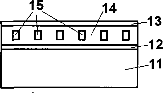
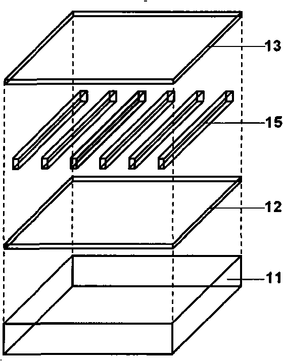
[0024] Figure 1~2 A schematic diagram of Embodiment 1 of the unit structure of an array microresonator tunable integrated optical filter is given. The structure is provided with a substrate 11, and a lower metal film 12 is arranged on the substrate 11. On the lower metal film 12, there is a dielectric layer 14 in which a one-dimensional metal grating 15 is embedded. On the dielectric layer 14, there is an upper metal film. 13. Substrate 11 can be selected as transparent dielectric substrate or semiconductor substrate (semiconductor substrate wherein can be the semiconductor chip that has made optoelectronic device); Lower layer metal film 12, upper layer metal film 13 and metal grating layer 15 can be selected as gold , silver, copper and aluminum and other good conductor metal materials; the dielectric layer 14 can be selected from high transmitta...


PUM


Abstract

The invention discloses an adjustable integration optical filter with an array type micro-resonator, relating to an optical filter and providing a realizable array type micro-resonator based on the existing micro-nano processing technique. The optical filter is provided with a substrate, a lower layer metallic film is arranged on the substrate, a dielectric layer is arranged on the lower layer metallic film, a metal grating layer is embedded in the middle of the dielectric layer and an upper layer metallic film is arranged on the dielectric layer. The metal grating layer is provided with a plurality of array units and the cycle of the metal grating in different array units is different. As the layer of dielectric layer embedded with the metal grating is arranged between the two layers of metallic films on the substrate and the metal grating in different integration units on a chip plane has different cycles, the equivalent refractive index in different units is regulated. When light wave goes through the adjustable integration optical filter of array type micro-resonator, different array units have different resonance wavelengths, therefore, a transmission passband is formed within certain wave spectrum width close to the resonance wavelength for the purpose of filtering.

Description

technical field [0001] The invention relates to an optical filter, in particular to a resonant cavity based on a metal micro-nano structure, which is used for an array type micro-resonant cavity tunable integrated optical filter for an integrated micro-optical system. Background technique [0002] With the development of science and technology and people's demand for high performance, intelligence and portability of optoelectronic products in production and life, the miniaturization and integration of related devices has become an important topic of research and development. Among them, the optical filter is an important part of the optoelectronic system. Especially the tunable integrated optical filter prepared on the chip, for color display (see literature: 1, B.Y.Jung, N.Y.Kim, C.Lee, C.K.Hwangbo, and C.Seoul, Appl.Opt.41, 3312( 2002); 2. S.Han, C.Huang, and Z.H.Lu, J.Appl.Phys.97, 093102 (2005); 3. H.Zhang, J.Shi, W.Wang, S.Guo, M. Liu, H.You, and D.Ma, J.Lumin., 122-1...

Claims


Application Information

Patent Timeline
Patent Type & Authority Applications(China)
IPC IPC(8): G02B6/34G02B6/12
Inventor 孙志军
Owner XIAMEN UNIV
Why Eureka
Try Eureka