Tunable laser
a laser and tunable technology, applied in the field of tunable lasers, can solve the problems of difficult to maintain the laser oscillation with a constant wavelength, high price due to an increase in the number of elements, and difficult to put them into practical use, so as to achieve high reliability, reduce the influence of stray light, and simplify the manufacturing process
- Summary
- Abstract
- Description
- Claims
- Application Information
AI Technical Summary
Benefits of technology
Problems solved by technology
Method used
Image
Examples
first embodiment
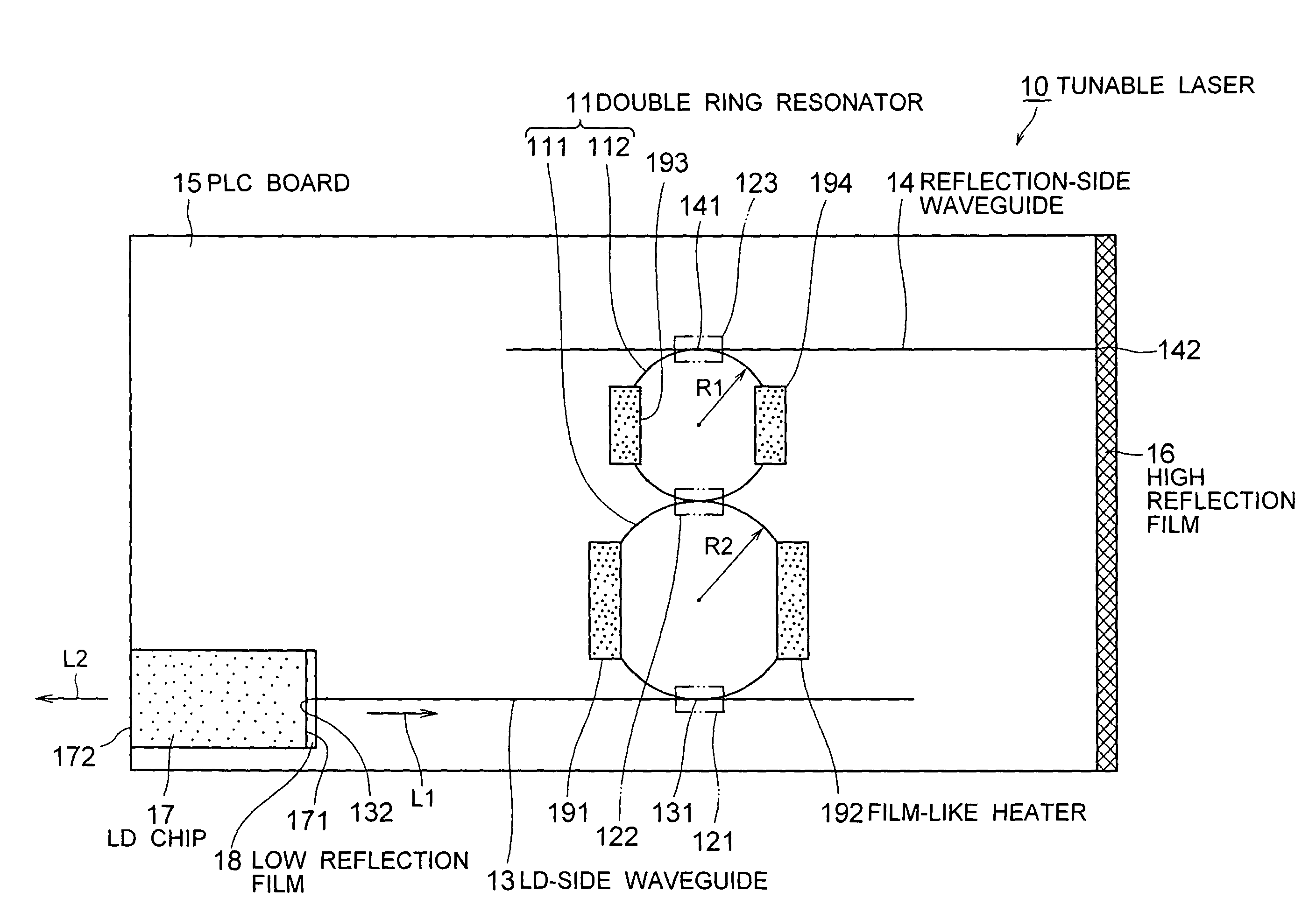
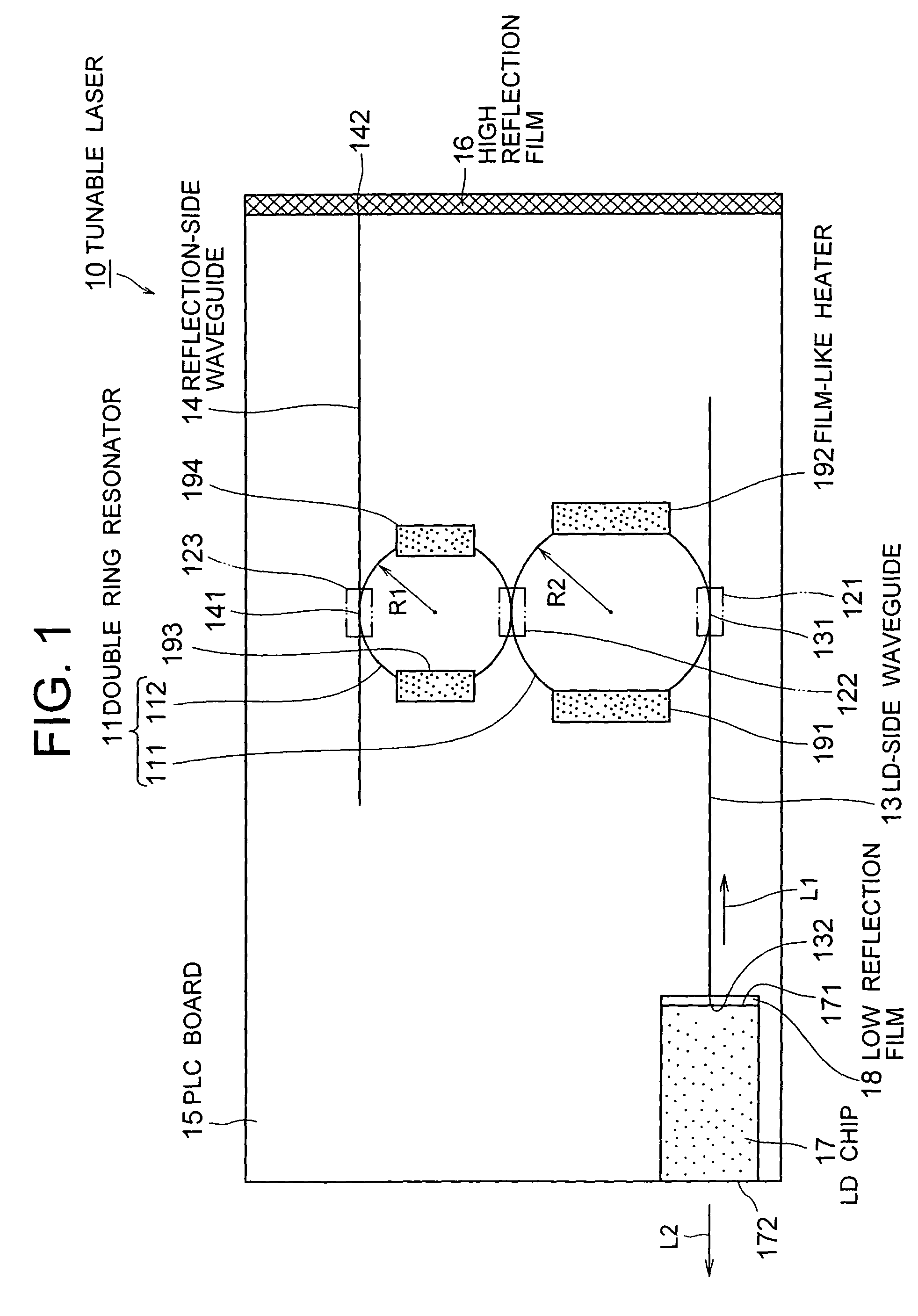
[0038]FIG. 1 is a plan view for showing the tunable laser according to the present invention. There will be a description provided hereinafter by referring to this illustration.
[0039]A tunable laser 10 according to this embodiment comprises: a double ring resonator 11 in which ring resonators 111, 112 that are formed with ring-type waveguides of different optical path lengths from each other are coupled through a directional coupler 122; an LD-side waveguide 13 whose one end 131 is connected to the ring resonator 111 through a directional coupler 121; a reflection-side waveguide 14 whose one end 141 is connected to the ring resonator 112 through a directional coupler 123; a single PLC board 15 on which the ring resonators 111, 112, the LD-side waveguide 13, and the reflection-side waveguide 14 are formed; a high reflection film 16 provided on other end 142 of the reflection-side waveguide 14; an LD chip 17 formed on the PLC board 15, which has a low reflection film 18 formed on one ...
second embodiment
[0052]FIG. 4 is a plan view for showing the tunable laser according to the present invention. There will be description provided hereinafter by referring to the drawing. The same reference numerals are applied to the same components as those of FIG. 1, and the description thereof will be omitted.
[0053]The tunable laser 20 according to this embodiment comprises bent parts 134, 144 formed at one end 131 of the LD-side waveguide 13 and one end 141 of the reflection-side waveguide 14 for directing, towards a prescribed direction, the end faces 133, 143 that are extended therefrom. With this, stray lights emitted from the end faces 134 and 143 can be guided towards the direction of less influence.
[0054]The bent parts 134 and 144 are used as the stray light suppressing parts in FIG. 4. However, it is not intended to be limited to those. Any stray light suppressing parts may be used as long as they can suppress the influence of the stray lights emitted from the end face that is extended fr...
third embodiment
[0055]FIG. 5 is a plan view for showing the tunable laser according to the present invention. There will be description provided hereinafter by referring to the drawing. The same reference numerals are applied to the same components as those of FIG. 1, and the description thereof will be omitted.
[0056]The tunable laser 30 according to this embodiment comprises a light-receiving element 31 provided on the end face 133 that is extended from one end 131 of the LD-side waveguide 13. The intensity of the laser light L2 emitted from the LD chip 17 can be monitored with the light-receiving element 31. The light-receiving element 31 is a photodiode, for example, and it is directly mounted on the PLC board 15 along with the LD chip 17 by the passive alignment technique. The light-receiving element 31 may be provided to the end face 143 that is extended from one end 141 of the reflection-side waveguide 14.
PUM
| Property | Measurement | Unit |
|---|---|---|
| wavelengths | aaaaa | aaaaa |
| temperatures | aaaaa | aaaaa |
| wavelength | aaaaa | aaaaa |
Abstract
Description
Claims
Application Information
 - R&D
- Intellectual Property
- Life Sciences
- Materials
- Tech Scout
- Unparalleled Data Quality
- Higher Quality Content
- 60% Fewer Hallucinations
Browse by: Latest US Patents, China's latest patents, Technical Efficacy Thesaurus, Application Domain, Technology Topic, Popular Technical Reports.
© 2025 PatSnap. All rights reserved.Legal|Privacy policy|Modern Slavery Act Transparency Statement|Sitemap|About US| Contact US: help@patsnap.com


