Premix burner arrangement with catalytic combustion and method for its operation

a burner arrangement and catalytic combustion technology, applied in the direction of combustion using catalytic materials, combustion using lumps and pulverulent fuels, combustion types, etc., can solve the problems of high lean extinction limits, vibration or pulsation in the combustion chamber, and great disadvantages of flame stability, etc., to reduce the flow cross-section

Inactive Publication Date: 2003-09-30
GENERAL ELECTRIC TECH GMBH
View PDF18 Cites 33 Cited by
  • Summary
  • Abstract
  • Description
  • Claims
  • Application Information

AI Technical Summary

Benefits of technology

Around the area 51 of the mixing pipe 5, a catalyst unit 8 is provided, which completely surrounds the mixing pipe area 51 in a circular manner. The catalyzer unit 8 is preceded in flow direction by branch-off channel 9 that also extends in a completely circular manner inside the mixing pipe 5, through which branch-off channel the peripheral portion of the fuel / air mixture inside the mixing pipe 5 is removed in the direction towards the catalyzer unit 8. The main portion of the fuel / air mixture passes unhindered axially through the mixing pipe 5 and is ignited inside the combustion chamber 6. The forcibly removed peripheral fuel / air mixture flows passing through the catalyzer unit 8 are converted by the latter at least in part thermally and / or chemically by catalytic action, and after exiting from the catalyzer unit 8 immediately enter the combustion chamber 6, where they meet the peripheral areas of the flame front 7 and are able to stabilize it.
In contrast to the previously described embodiment, a catalyzer unit 8 is provided at the donstream end of the mixing pipe 5 in such a way that catalyzer material projects into the peripheral edge areas inside the mixing pipe 5 and reduces the flow cross-section through the mixing pipe 5. The catalyzer unit 8 is constructed of a porous material coated with catalyzer unit so hat peripheral flow portions of the fuel / air mixture spreading inside the premix burner unit forcibly flow through the catalyzer unit 8, in which they are at least in part converted calytically. The catalytic conversion takes place either thermally and / or chemically and, in addition to a decisive reduction of NOx emission values, also contributes to the stabilization of the flame front forming inside the combustion chamber.

Problems solved by technology

Furthermore, so-called combustion chamber vibrations occur during the operation of known premix burner arrangements, to the great disadvantage of flame stability.
Such combustion chamber vibrations or pulsations have a particularly disadvantageous effect in operating states where lean fuel / air mixtures are used.
This results in high lean extinction limits, i.e., an extinction of the flame in spite of relatively high fuel content, causing the operating range of the premix burner to be greatly limited, especially with respect to a lean operation.
Previous approaches and attempts to combine premix burner arrangements with catalyzers in order to reduce at least the previously mentioned NOx emissions in the combustion process failed or provided only unsatisfactory results, especially since the usual use of liquid fuel, for example oil, for firing such premix burner arrangements makes catalyzers known per se unusable because it obstructs the catalyzer openings.

Method used


Image

  • Premix burner arrangement with catalytic combustion and method for its operation
  • Premix burner arrangement with catalytic combustion and method for its operation
  • Premix burner arrangement with catalytic combustion and method for its operation

Examples


Embodiment Construction

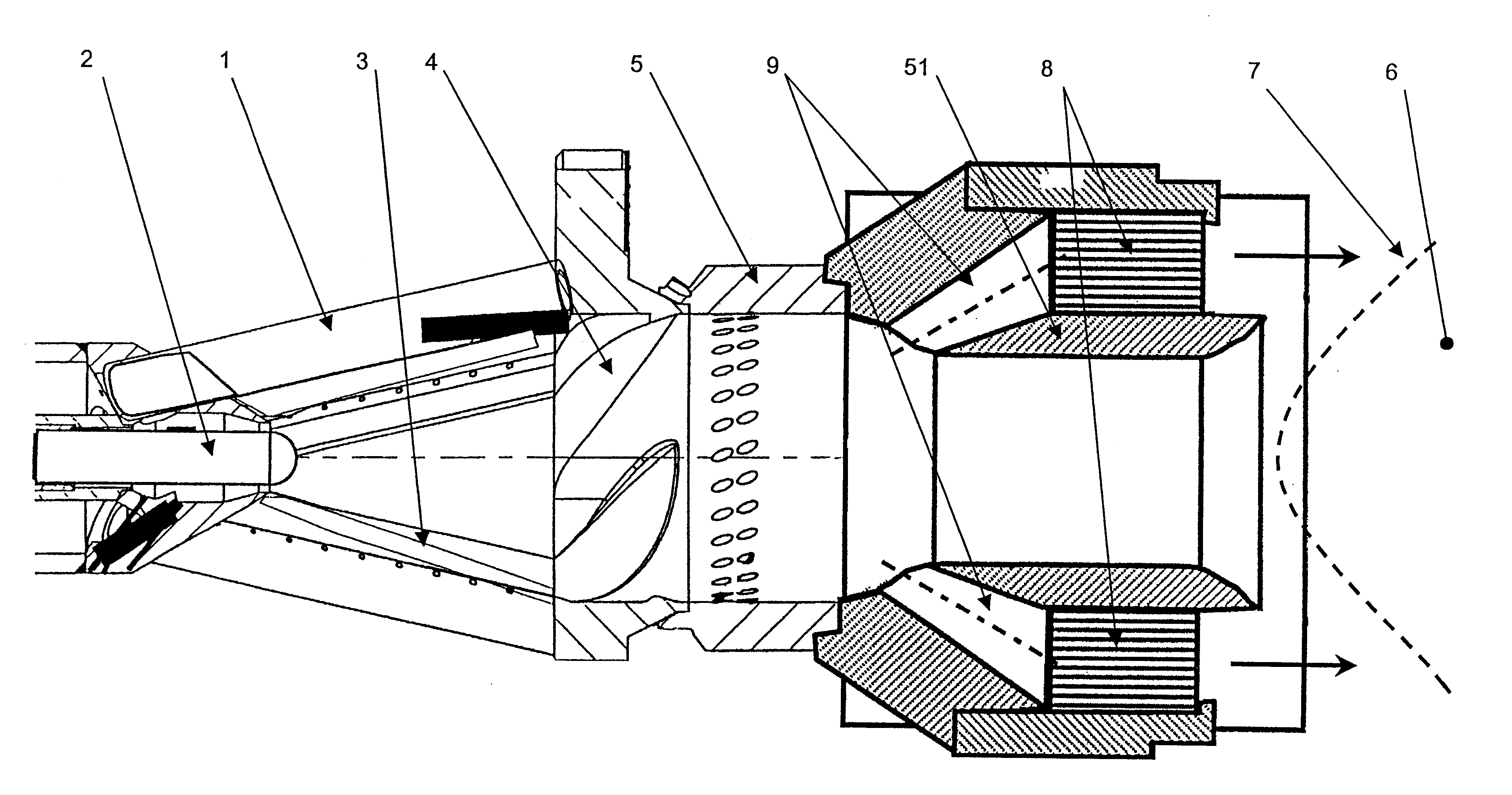
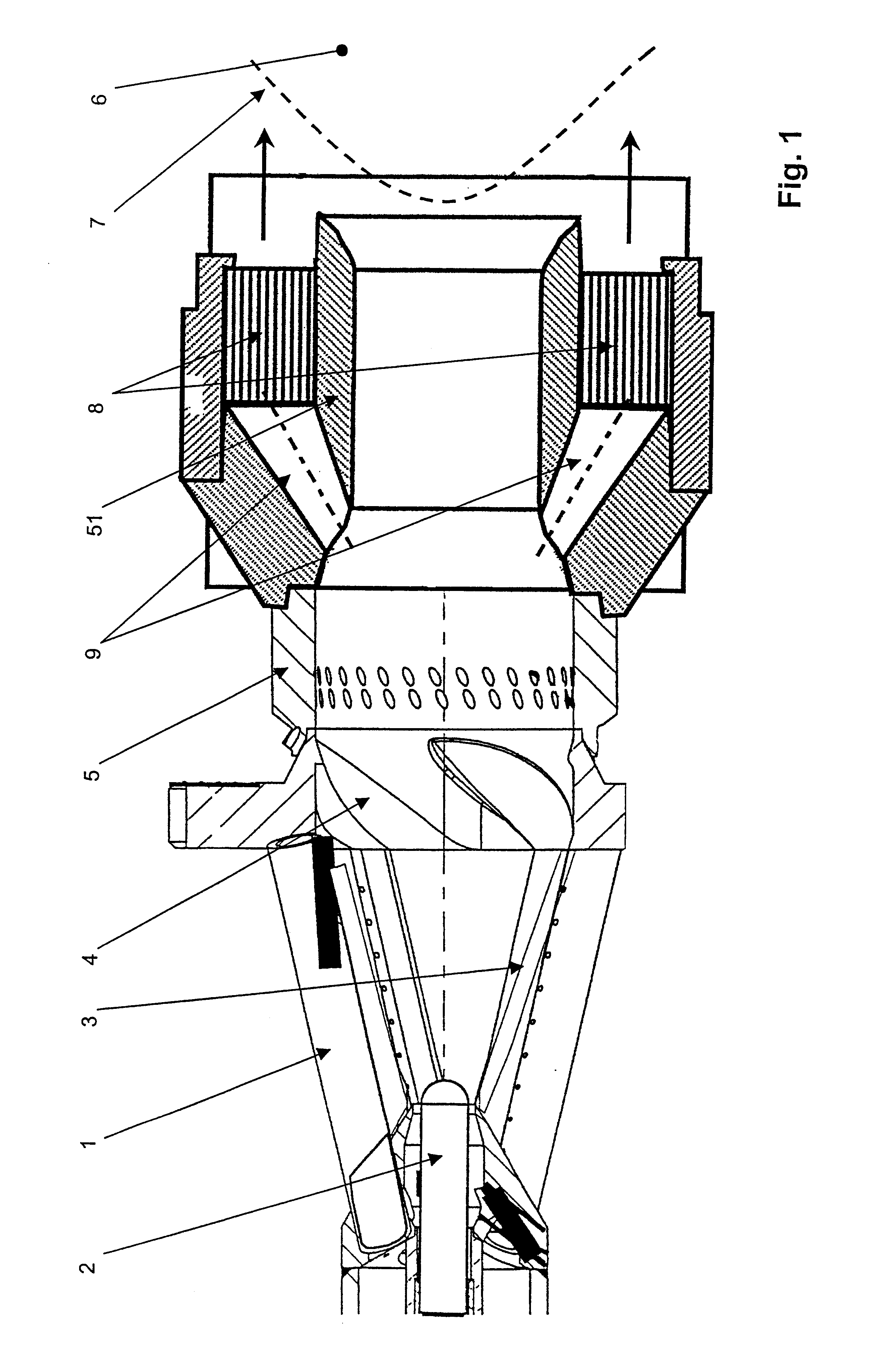
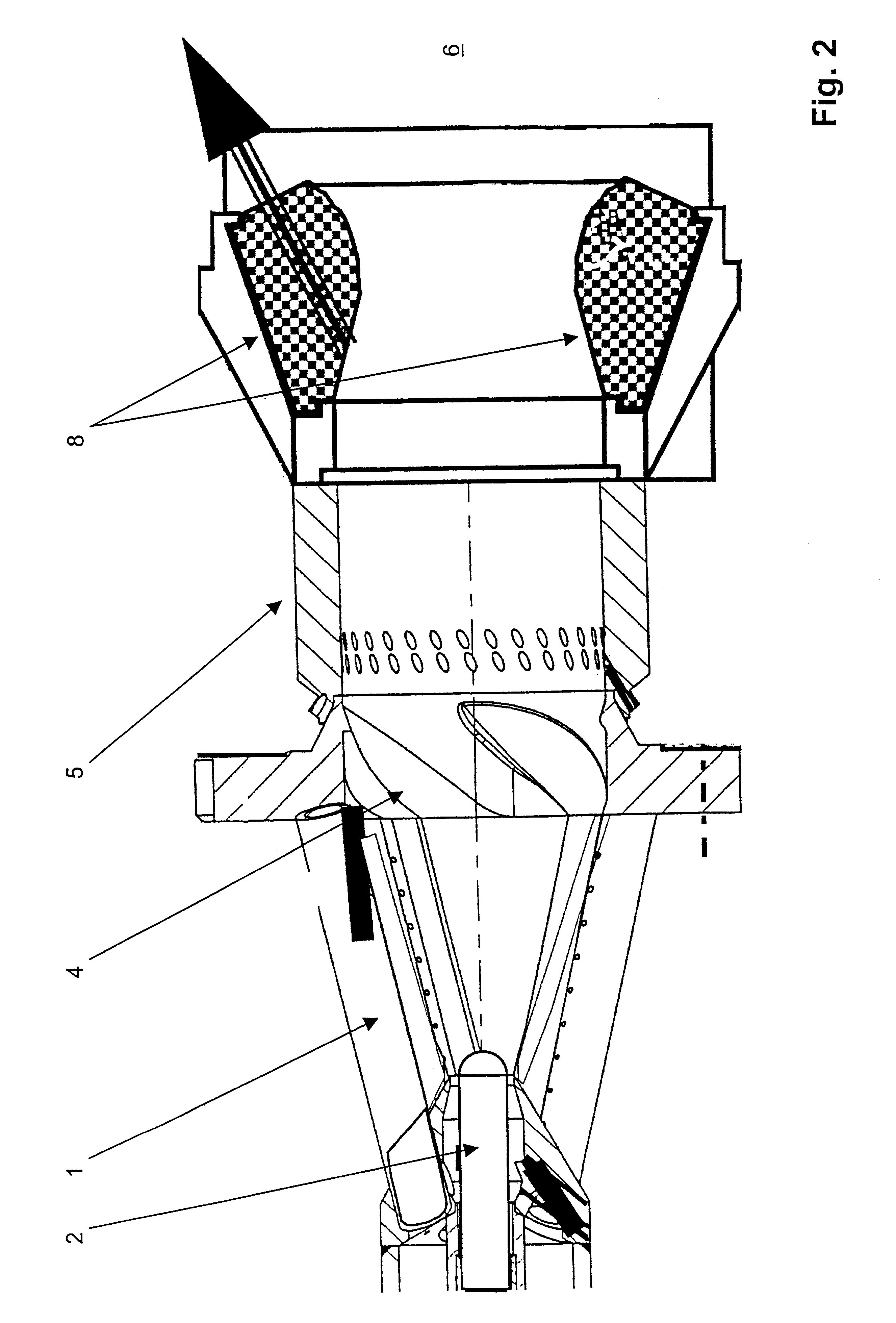
The invention is based on the objective of further developing a premix burner arrangement with catalytic combustion for operating a combustion chamber of a gas turbine arrangement according to the preamble of claim 1 in such a way that on the one hand, measures are implemented through which the NOx emission values are supposed to be substantially reduced. And in addition, the measures should result in flame stabilization within the combustion chamber so that the operating ranges of the premix burner arrangement are expanded, in particular with respect to an improved lean extinction limit.

The realization of the objective of the invention is disclosed in claim 1. The subject of claim 9 is a method for operating a premix burner arrangement with catalytic combustion. Characteristics that advantageously further develop the concept of the invention are the subject of the secondary claims and specification in reference to the exemplary embodiments.

According to the invention, a premix burne...


PUM


Abstract

A premix burner arrangement with catalytic combustion provides a fuel / air mixture to a combustion chamber of a gas turbine arrangement. The premix burner arrangement includes a premix burner, at least one fuel addition unit, and air inlet openings arranged in such a way that at least one of gaseous and liquid fuel can be mixed with combustion inlet air inside the premix burner to form a fuel / air mixture. The fuel / air mixture exits from the premix burner downstream in the direction towards a combustion chamber positioned after the premix burner arrangement and can be ignited inside the combustion chamber. A catalyzer unit is provided before the entrance of the fuel / air mixture into the combustion chamber. Part of the fuel / air mixture can be introduced into and passed through the catalyzer unit before the catalyzed part of the fuel / air mixture flows together with the remaining portion of the fuel / air mixture into the combustion chamber.

Description

FIELD OF TECHNOLOGYThe invention relates to a premix burner arrangement with catalytic combustion for operating a combustion chamber of a gas turbine arrangement, as well as a method to this effect, having a premix burner, wherein at least one fuel addition unit as well as inlet air openings have been provided in such a way that gaseous and / or liquid fuel can be mixed with combustion inlet air inside the premix burner and form a fuel / air mixture, which exits from the premix burner downstream in the direction towards the combustion chamber positioned after the premix burner arrangement and which can be ignited inside the combustion chamber.STATE OF THE ARTA premix burner arrangement of this type is disclosed in EP 0 833 105 A2. The premix burner described in this document is provided with a central fuel nozzle axially towards the swirl generator, said swirl generator being followed downstream by a mixing section in which the atomized fuel is mixed completely with air to form a fuel / a...

Claims


Application Information

Patent Timeline
Patent Type & Authority Patents(United States)
IPC IPC(8): F23R3/40F23R3/28F23R3/00F23C13/00F23C99/00F23D11/40F23D14/18F23R3/30
CPCF23R3/286F23R3/40F23C2900/07002F23C2900/9901
Inventor WEISENSTEIN, WOLFGANGGRIFFIN, TIMOTHY ALBERTJANSOHN, PETERRUCK, THOMAS
Owner GENERAL ELECTRIC TECH GMBH
Why Eureka
Try Eureka