Disk reproducing speed control method and a disk reproducing apparatus using this method

a disc reproducing and speed control technology, applied in the field of disc reproducing speed control method and disk reproducing apparatus using this method, can solve the problems of disc reproducing apparatus moving across, centering eccentricity imbalance, failure to operate,

Inactive Publication Date: 2003-10-07
HITACHI CONSUMER ELECTRONICS CORP
View PDF38 Cites 17 Cited by
  • Summary
  • Abstract
  • Description
  • Claims
  • Application Information

AI Technical Summary

Problems solved by technology

Such deviated gravity disc may be generated during manufacturing, for example, because a disc material pressure is uneven, an unbalanced paint distribution is applied to a surface of the disc, or by reason that an index label is attached on the disc surface after manufacturing thereby to imbalance the disc.
Such vibration can result in a failure of operation (e.g., burn out, mis-reading, etc.) of the disc reproducing apparatus, can have an adverse effect on components installed in close proximity to the vibrating disc, a noise generated therefrom can be an annoyance to a user, and / or vibration can cause the disc reproducing apparatus to move across a surface on which it is placed.
Another imbalance of interest to a smaller degree is a centering eccentricity imbalance, i.e., a centering eccentricity imbalance of the disc, causable of at least one of a radial oscillation and radial vibration above a predetermined rotational speed, i.e., oscillation / vibration directed along a radial direction (i.e., in a major plane) of the disc so as to cause a disc to fling side-to-side as the disc is rotated.
Centering eccentricity imbalance results, for example, when a disc is loaded with its disc center misaligned to a center of a rotator arrangement (i.e., rotating motor, disc mount / clamp, etc.).
Misalignment may be due to sloppy loading of the disc to the mount / clamp, excessively sized central mounting hole in the disc, excessively small or worn mount / clamp, etc.
Centering eccentricity imbalance affects oscillation / vibration and operation of the disc reproducing apparatus to a lesser degree than that of mass eccentricity imbalance.
However, in practice stopping the pickup opposed to a desired track may not be practical because a track location may oscillate (due to eccentricity as described above and below) and because there is a limit in the quantity of displacement (fine adjustment) of a beam L by the tracking arrangement.
However, when rotational speed is increased to a high rotational speed, for example 8.times. or 12.times. (in order to accomplish high speed reproduction), the disc reproducer may experience oscillation / vibration and track eccentricity in a direction parallel to a major plane of the disc.
More particularly, oscillation / vibration and track eccentricity may be only experienced or increased as rotational speed is increased.
For track eccentricity below a predetermined value, tracking control and track following can still be accomplished, but if above the predetermined value, tracking control and track following cannot be accomplished.
Though it varies depending upon the quantity of mass eccentricity, according to experiments, when reproduction is executed at approximately a 6.times.rate or more, oscillation / vibration, track eccentricity and noise occurs.
Therefore, in the case of reproduction of a mass eccentric disc at an 8.times.rate which is the recent mainstream, a large oscillation / vibration, track eccentricity and noise are generated by the disc reproducer, undesirable oscillation may be applied to components installed in close proximity to the disc, and such oscillation may have a detrimental effect upon components of and work around this disc reproducer.
However, when this tracking control is stopped, the condenser held by the elastic member is oscillated by and in synchronization with the disc imbalance vibration.
As explained above, when an imbalanced disc is rotated / reproduced at high reproduction rates (e.g., 8.times., 12.times.), vibration becomes large.

Method used


Image

  • Disk reproducing speed control method and a disk reproducing apparatus using this method
  • Disk reproducing speed control method and a disk reproducing apparatus using this method
  • Disk reproducing speed control method and a disk reproducing apparatus using this method

Examples


first embodiment

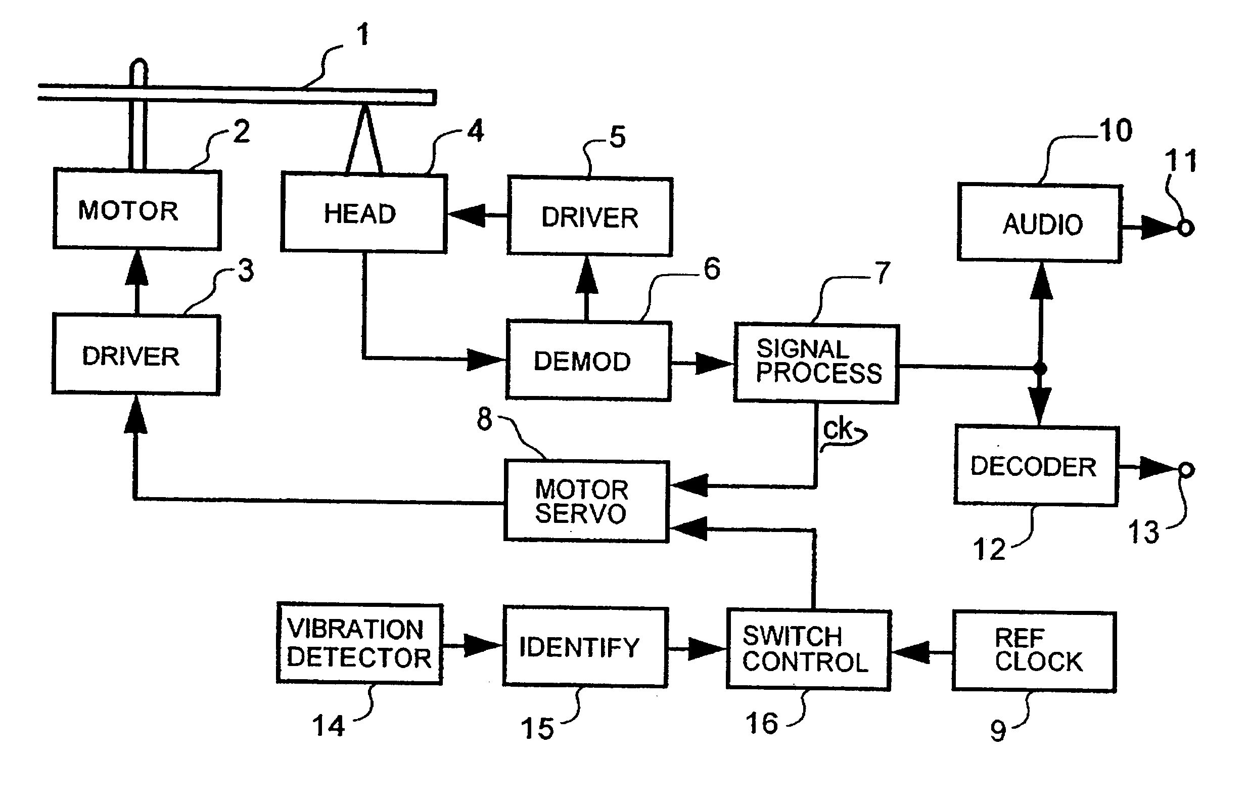
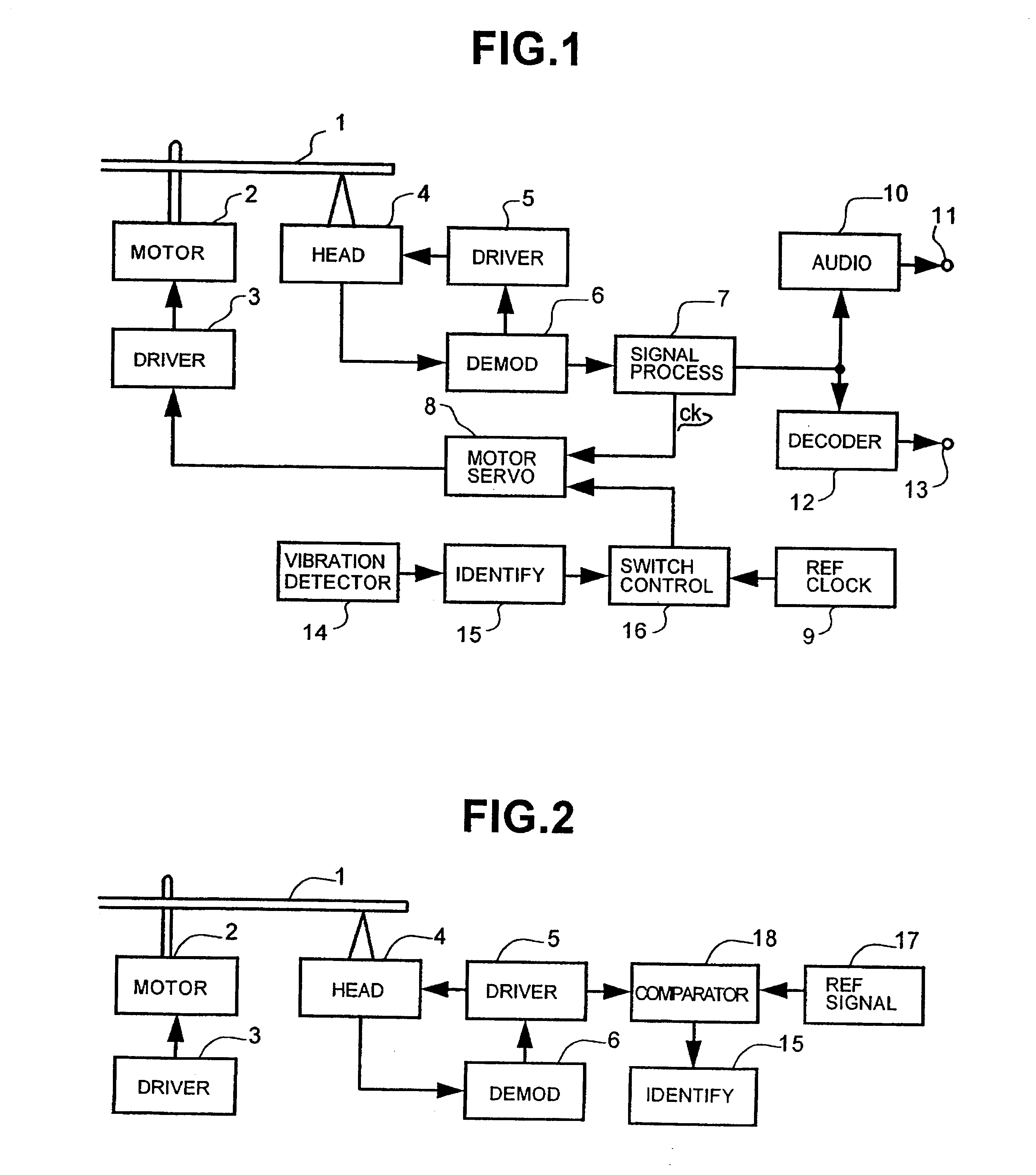
Turning now to detailed description of the invention, FIG. 1 is a block diagram of a disc reproducing apparatus according to the present invention. More particularly, in FIG. 1: reference numeral 1 designates a disc; 2, a disc motor; 3, a disc motor driving circuit; 4, an information reader (i.e., head assembly) comprising a transfer arrangement; 5, a transfer driving circuit for controlling and driving the transfer arrangement of the information reader 4; 6, a demodulating circuit for demodulating signals from the information reader 4; 7, a signal processing circuit; 8, a disc motor servo circuit; 9, a reference clock generating circuit; 10, an audio circuit; 11, an audio output terminal; 12, a CD-ROM decoder, 13, a CD-ROM signal output terminal; 14, a vibration detector for detecting vibration of the disc reproducing apparatus; 15, a vibration identifier; 16, a reproducing rate switching controller comprising a frequency dividing circuit for dividing the frequency of the reference...

second embodiment

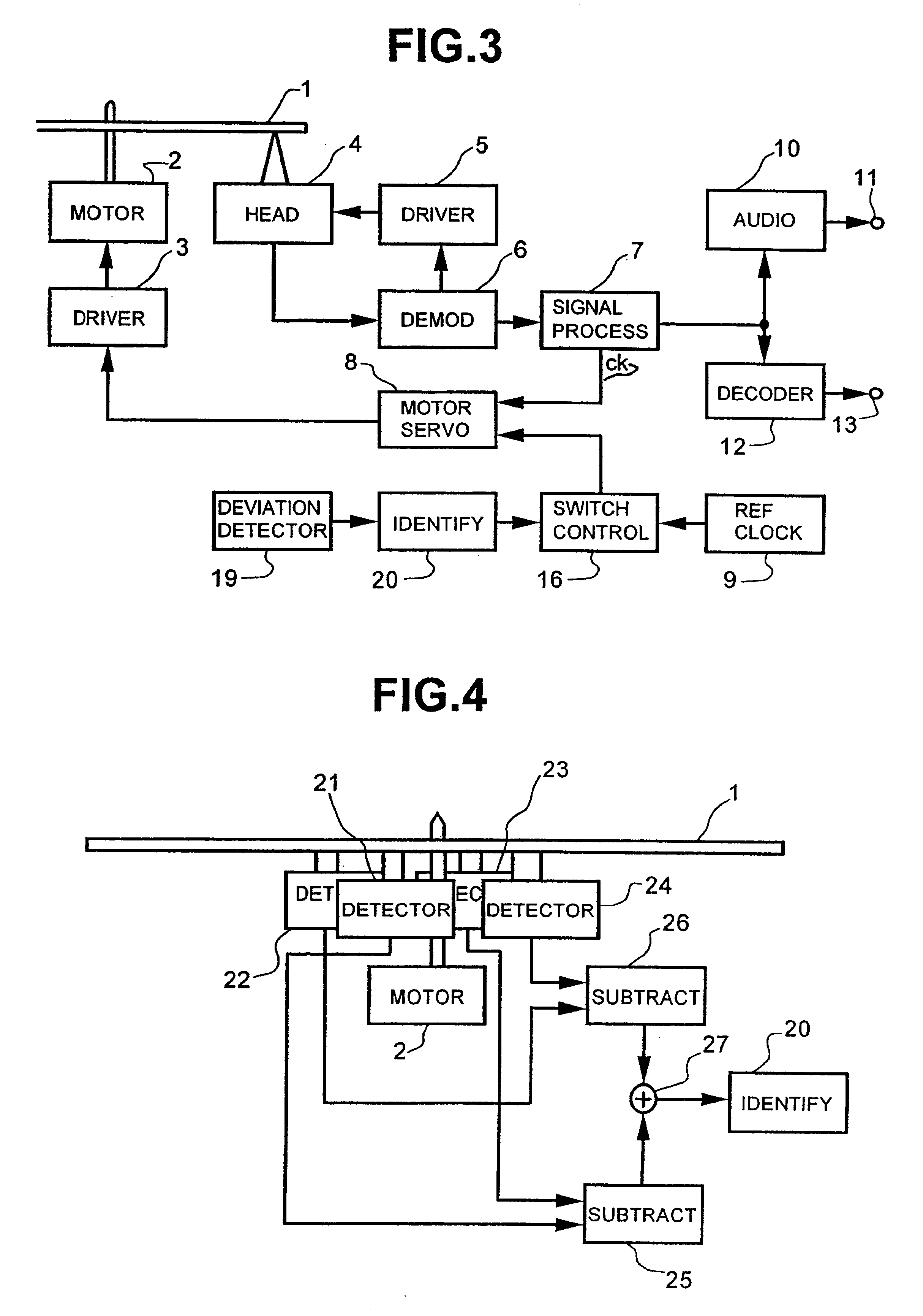
FIG. 3 shows the present invention considering the above initial low speed approach. More particularly, in FIG. 3, the reference numeral 19 designates a deviated gravity detector for detecting deviation of gravity of disc 1 and outputting a signal depending on such amount of gravity deviation, and 20 designates a deviated gravity identifier for identifying an output signal from the deviated gravity detector 19. Other portions designated by like reference numerals to those in FIG. 1 indicate like components.

The deviated gravity identifier 20 judges, when the output signal from the deviated gravity detecting 19 exceeds a predetermined value, that a deviation of gravity of disc 1 is large and outputs a control signal to limit a reproducing rate to a lower rate. The reproducing rate switching control 16 limits the dividing ratio of the reference clock signal outputted from the reference clock generating circuit 9 depending on the control signal from the deviated gravity identifier 20. T...


PUM

PropertyMeasurementUnit
rotational speedaaaaaaaaaa
frequencyaaaaaaaaaa
speedaaaaaaaaaa

Abstract

When a deviated gravity disc is reproduced at a higher rate with the disc reproducing apparatus, an excessive vibration is generated and this vibration gives adverse effect on the disc reproducing apparatus and peripheral components / apparatuses, and / or may represent an annoyance to a user. A vibration information detector for detecting vibration of the disc reproducing apparatus or a deviated gravity information detector for detecting amount of gravity deviation of disc is provided, and as a result of such detection of an imbalance (i.e., excessive vibration or mass eccentricity), and a reproducing rate switching control controls sets and limits the reproducing rate of the disc reproducing apparatus to a substitute speed which is lower or higher than a normal reproducing speed.

Description

1. Field of the InventionThe present invention generally relates to a disc reproducing method and apparatus which utilize a disc motor for rotating a disc and an optical pickup to realize high speed reproduction, and more particularly relates to a disc reproducing method and apparatus which are suitable for prevention of excessive oscillation and / or vibration in a radial direction of a disc during high speed rotation resulting from an imbalance (e.g., disc eccentricity imbalance, mass imbalance, etc.).2. Description of Related ArtUse of a so-called compact disc--read only memory (CD-ROM) apparatus (utilizing CD-ROM's as recording / reproduction medium) as a peripheral device of a personal computer has gained in popularity and frequency in recent years. Since introduction, whereupon the CD-ROM apparatus was standardized to operate at a predetermined 1.times.speed or rate, technology has advanced tremendously, leading to ever increasing operating speeds for the CD-ROM apparatus, i.e., f...

Claims


Application Information

Patent Timeline
Patent Type & Authority Patents(United States)
IPC IPC(8): G11B19/26G11B7/095
CPCG11B19/26G11B7/0953G11B7/005G11B19/042G11B19/2027G11B19/28G11B2220/2529G11B2220/2545G11B2220/2562
Inventor FUKUDA, HIROTOSHINARITA, KAZUNAGATERAMOTO, KIYONOBUISHIBASHI, HIROHITOMATSUNAGA, TOSHIHIROSANO, MASATO
Owner HITACHI CONSUMER ELECTRONICS CORP
Why Eureka
Try Eureka