Apparatus for damping acoustic vibrations in a combustor

a technology of acoustic vibration and combustor, which is applied in the direction of combustion air/fuel air treatment, lighting and heating apparatus, instruments, etc., can solve the problems of inability to provide exact frequencies, inability to pre-determine frequency to be damped with the required accuracy,

Inactive Publication Date: 2003-10-21
ANSALDO ENERGIA IP UK LTD
View PDF22 Cites 57 Cited by
  • Summary
  • Abstract
  • Description
  • Claims
  • Application Information

AI Technical Summary

Problems solved by technology

However, when used in gas or steam turbines, the problem occurs that the frequency to be damped is not determined by intermittent combustion but by fulfilling the Rayleigh criterion in the combustor and by the acoustic response of the surrounding system comprising the supply line, burner, combustor, and acoustic terminus.
In these systems, the frequency to be damped therefore cannot be predetermined with the required accuracy by using the mathematical tools currently available.
Furthermore, the acoustical behavior of the system and thus the frequencies of the vibrations to be damped may critically change when the operating point is changed, so that it may become necessary to use additional resonators that are adapted to additional frequencies.
However, here again the optimal sizing of the various Helmholtz resonators requires knowledge regarding the frequencies occurring during the operation of the system, where again exact frequencies cannot be provided when the system is being built.
Furthermore, the arrangement of several Helmholtz resonators is disadvantageous due to the additional space needed for this purpose.
But such a solution is completely unsuitable for use in the pressure range found in modern industrial gas turbines.
The passing of a mechanical gear through the pressure container of a gas turbine would inevitably cause leaks and result in intolerable losses.
The temperature influences associated with industrial gas turbines also could only be compensated for with a very complex gear.

Method used


Image

  • Apparatus for damping acoustic vibrations in a combustor
  • Apparatus for damping acoustic vibrations in a combustor

Examples


Embodiment Construction

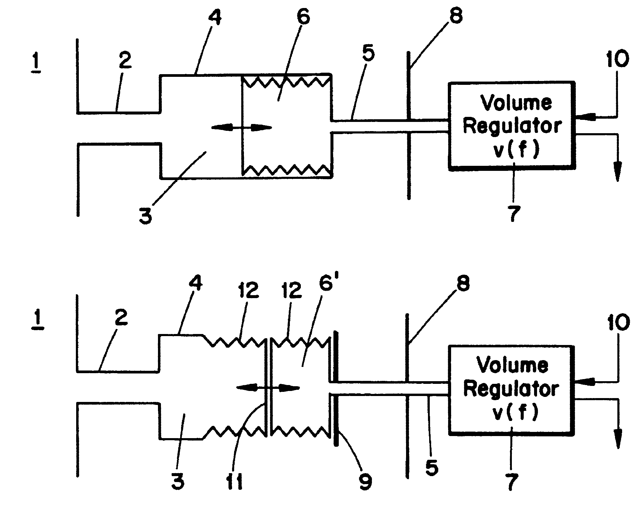
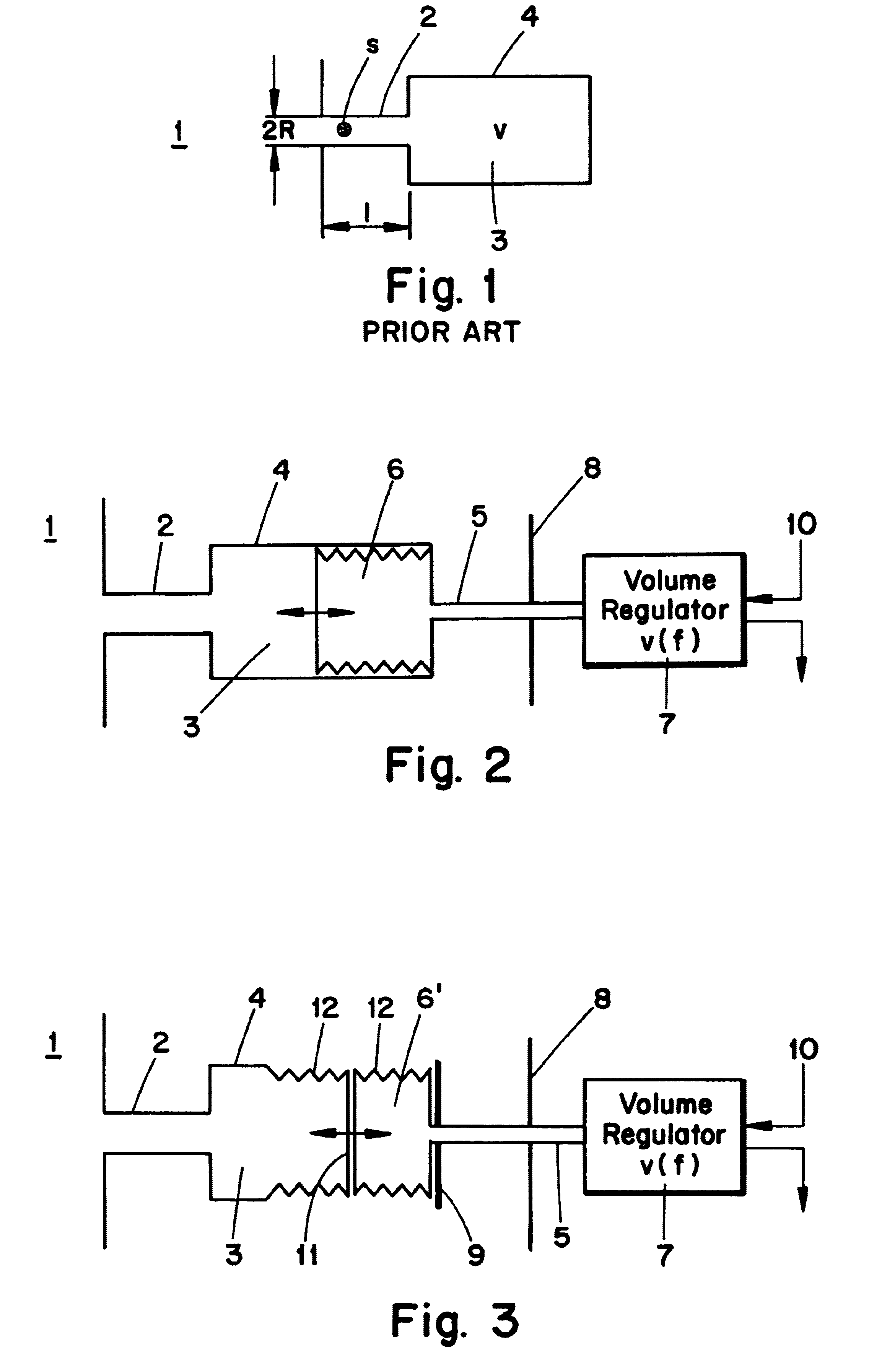
The apparatus includes a Helmholtz resonator with a connecting channel that is connected to the combustor, for example, the combustor of a gas turbine. In contrast to the known damping devices, the present apparatus is provided with a hollow body, the volume of which can be changed by adding or draining a fluid via a supply line, and which is arranged either within the Helmholtz resonator or is located adjacent to it in such a way that the resonance volume of the Helmholtz resonator changes when the volume of the hollow body changes.

When the adjustable-volume hollow body is located in the Helmholtz resonator, the resonance volume decreases when the hollow body is inflated via the supply line, for example with a gas. Correspondingly, the resonance volume of the Helmholtz resonator increases, when a certain amount of the gas is drained from the hollow body. The change in resonance volume in the known manner causes a change in the resonance frequency.

In this way, the resonance frequenc...


PUM


Abstract

An apparatus for damping acoustic vibrations in a combustor as well as a corresponding combustor arrangement with the apparatus. The apparatus includes a Helmholtz resonator (4) that can be connected via a connecting channel (2) with a combustor (1). The Helmholtz resonator (4) contains a hollow body (6) the volume of which can be changed by adding or draining a fluid via a supply line (5), or is located adjacent to such a hollow body in such a way that the resonance volume (3) of the Helmholtz resonator (4) is changed when the volume of the hollow body (6) is changed. This apparatus makes it possible to adjust the resonance frequency of a Helmholtz resonator arranged inside a pressure container in accordance with the respective current operating point of the combustor to be damped, without having to pass movable components through the pressure container.

Description

This application claims priority under 35 U.S.C. .sctn..sctn.119 and / or 365 to Appln. No. 100 26 121.3 filed in Germany on May 26, 2000; the entire content of which is hereby incorporated by reference.FIELD OF APPLICATIONThe present invention relates to an apparatus for damping acoustic vibrations in a combustor, as well as a combustor arrangement, in particular of a gas or steam turbine, that contains the apparatus.The main field of application of the present invention is the field of industrial gas turbines. Worldwide, increasingly higher requirements with respect to readiness, life span, and waste gas quality are placed on industrial gas turbines, especially when used in power plants. An increasing consciousness of environmental protection and environmental compatibility requires compliance with the lowest possible values for noxious emissions.Low emissions can only be achieved economically in industrial gas turbines by using premix burners. However, in closed combustors, because...

Claims


Application Information

Patent Timeline
Patent Type & Authority Patents(United States)
IPC IPC(8): F01N1/02F23M13/00F01D25/00F02C7/24F23M20/00
CPCF01N1/02F01N1/023F23M20/005F23D2210/00F23R2900/00014F01N2490/12
Inventor PASCHEREIT, CHRISTIAN OLIVERWEISENSTEIN, WOLFGANGFLOHR, PETERPOLIFKE, WOLFGANG
Owner ANSALDO ENERGIA IP UK LTD
Why Eureka
Try Eureka