Capacitance-type pressure sensor

a capacitance-type, pressure sensor technology, applied in the direction of fluid pressure measurement using capacitance variation, force measurement, instruments, etc., can solve the problem of increasing the so-called ineffective region which does not contribute to the formation of capacitance to be detected, the diaphragm size is too large, and the pressure measurement accuracy is difficult to achieve high accuracy

Inactive Publication Date: 2003-11-04
HITACHI LTD +1
View PDF6 Cites 74 Cited by
  • Summary
  • Abstract
  • Description
  • Claims
  • Application Information

AI Technical Summary

Benefits of technology

By virtue of the structure of the capacitance-type pressure sensor described above, ineffective region which does not contribute to the formation of the capacitance to be detected can be minimized with the parasitic capacitance being reduced, whereby the detection accuracy of the sensor can be enhanced significantly.
In another preferred mode for carrying out the invention, etching holes may be formed in the diaphragm for thereby forming the cavity region, which is advantageous in that the throughput of the manufacturing process can be enhanced.
In a further preferred mode for carrying out the invention, a conductive film may be deposited over a surface of a topmost film constituting the diaphragm so as to cover the diaphragm wholly. With this structure, the reliability as well as the detection accuracy of the sensor can be enhanced.
As is apparent from the foregoing, with the structures of the capacitance-type pressure sensor according to the present invention, ineffective region which plays no role in capacitance detection can be minimized, whereby the parasitic capacitance of the sensor can be reduced with the detection accuracy thereof being enhanced significantly.

Problems solved by technology

The first mentioned conventional technique suffers a problem that the size of the diaphragm which determines the pressure characteristic of the sensor may differ from one to another sensor due to dispersion in the etching condition because of formation of the cavities through partial etching of the auxiliary layer by way of the gaps formed in the diaphragm layer by resorting to a time-based control.
The increased parasitic capacitance in turn brings about a problem that difficulty is encountered in detecting the pressure with high accuracy.
Consequently, the so-called ineffective region which does not contribute to formation of capacitance to be detected increases, involving increased parasitic capacitance due to the ineffective region.
The increased parasitic capacitance in turn brings about difficulty in detecting the pressure with high accuracy, giving rise to a problem.

Method used


Image

  • Capacitance-type pressure sensor
  • Capacitance-type pressure sensor
  • Capacitance-type pressure sensor

Examples


embodiment 1

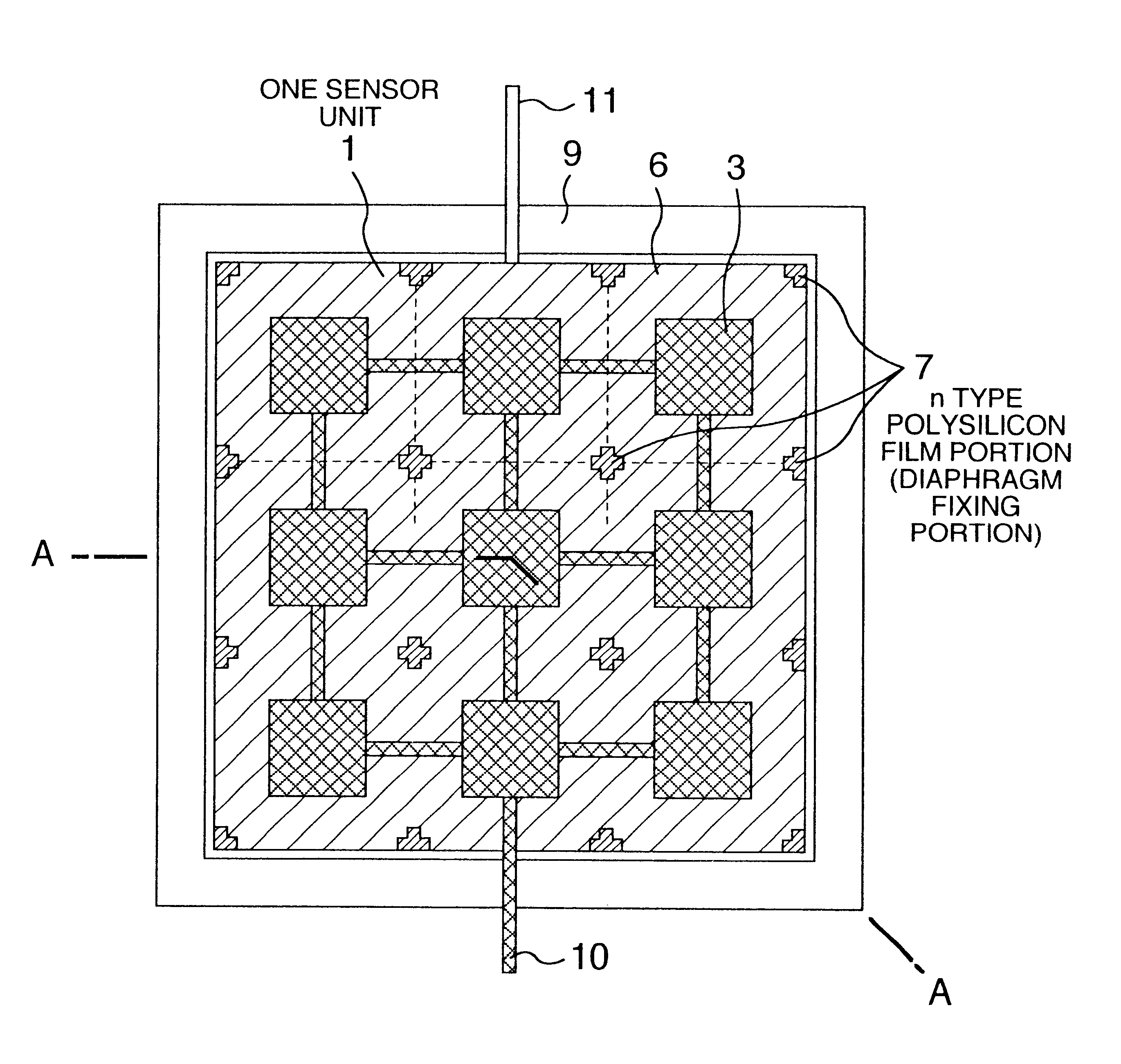
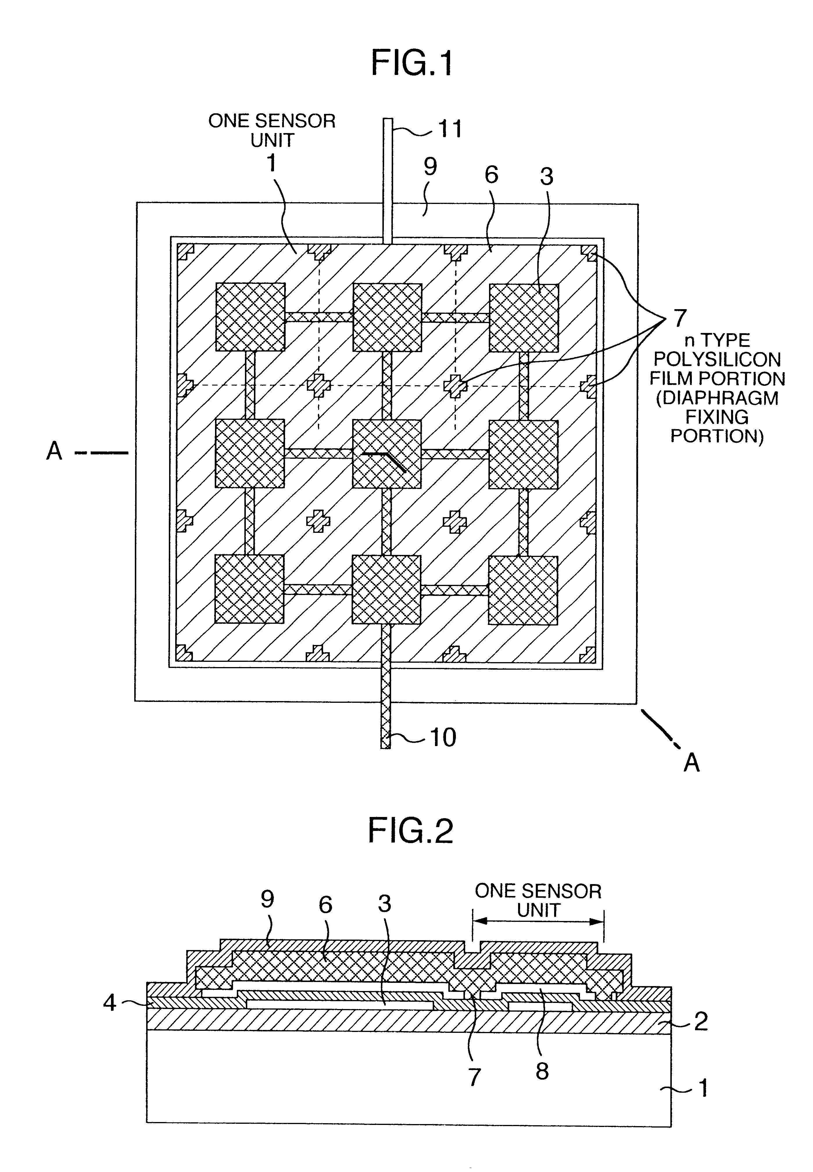
Now, description will be made of the capacitance-type pressure sensor according to a first embodiment of the present invention by reference to FIG. 1 and FIG. 2 in which FIG. 1 is a top plan see-through view of the capacitance-type pressure sensor and FIG. 2 is a sectional view of the same taken along a line A--A in FIG. 1.

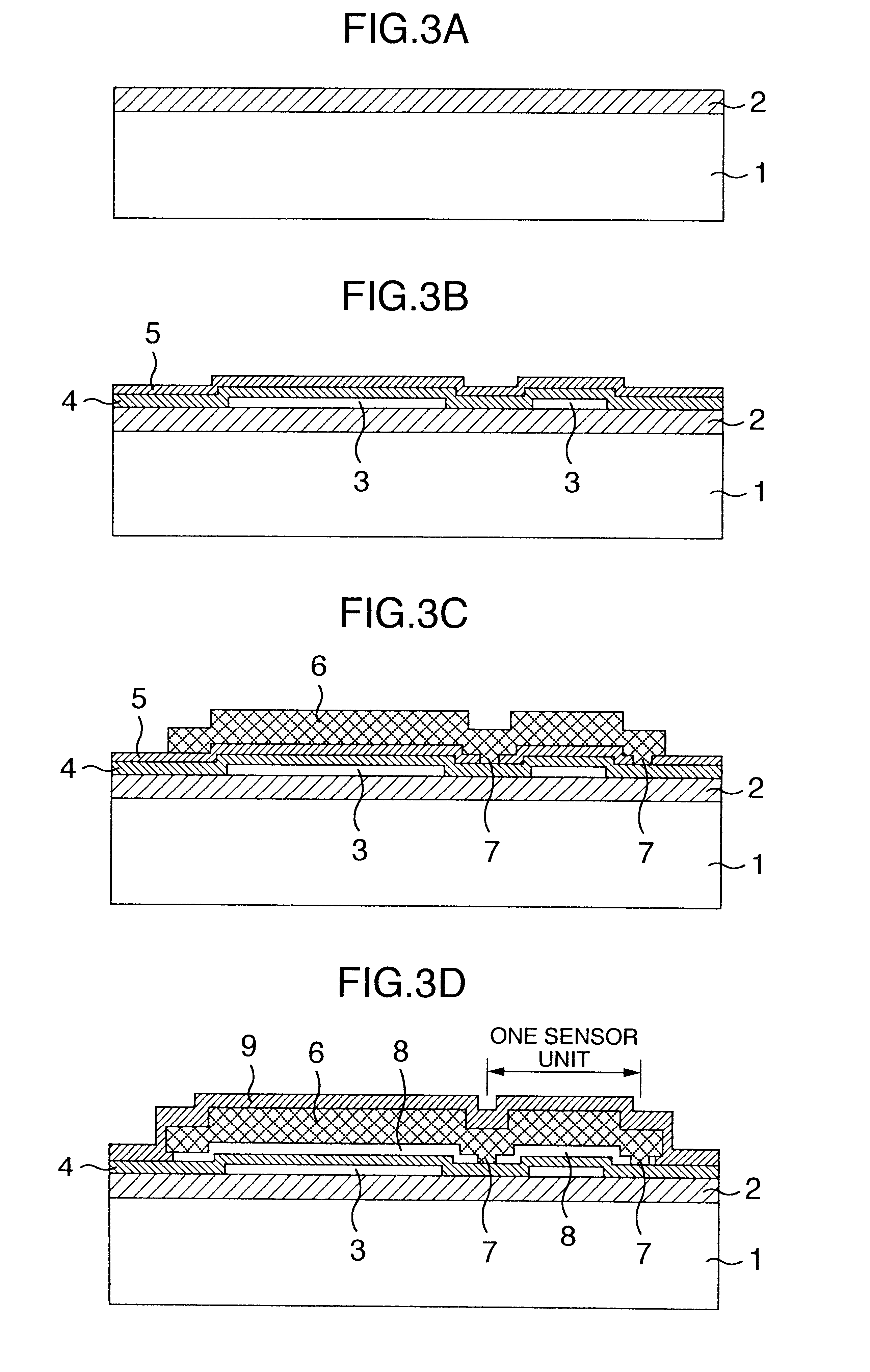
Referring to FIGS. 1 and 2, reference numeral 1 denotes a semiconductor substrate having one surface over which a silicon oxide film 2 is deposited as an insulation film. Disposed on the silicon oxide film 2 in a matrix-like pattern are n-type polysilicon films 3 which serve as electrodes (fixed electrodes), respectively, wherein the n-type polysilicon films 3 are electrically connected in parallel with one another, as can be seen in FIG. 1. Further formed or deposited over the silicon oxide film 2 and the n-type polysilicon films 3 is a silicon nitride film 4 as an insulation film which is to serve as an etching stopper when a cavity region 8 is formed.

Disposed i...

embodiment 2

Next, description will be directed to the capacitance-type pressure sensor according to a second embodiment of the present invention by reference to FIG. 4 and FIG. 5 in which FIG. 4 is a top plan see-through view of the capacitance-type pressure sensor and FIG. 5 is a sectional view of the same taken along a line A--A in FIG. 4.

Referring to FIGS. 4 and 5, the n-type polysilicon film portion 6 serving as the movable electrode is provided with etching holes 15 for forming the cavity region 8. The etching holes 15 are disposed on lines interconnecting the n-type polysilicon film portions 7 so that the size of diaphragm section supported by the n-type polysilicon film portions 7 and regionally partitioned thereby can remain uniform.

By etching the silicon oxide film by using the etching holes 15 to thereby form partitionarily the cavity region 8, the time required for etching is determined in dependence on the size of the sensor unit. Thus, the time required for forming the cavity regio...

embodiment 3

Description will be made of the capacitance-type pressure sensor according to a third embodiment of the present invention by reference to FIG. 6 and FIG. 7 in which FIG. 6 is a top plan see-through view of the capacitance-type pressure sensor now concerned and FIG. 7 is a sectional view of the same taken along a line A--A in FIG. 6.

Referring to FIGS. 6 and 7, in the capacitance-type pressure sensor according to the third embodiment of the invention, an n-type polysilicon film 20 is formed over the silicon oxide film 9 so that the n-type polysilicon film 20 serves as a shielding electrode for preventing intrusion of contaminants such as moisture, movable ions or the like and noise from the exterior.

Between the n-type polysilicon film 20 serving as the shielding electrode and the n-type polysilicon film portion 6 serving as the movable electrode, there makes appearance parasitic capacitance having dielectric constituted by the silicon oxide film 9. In this conjunction, it is noted tha...


PUM

PropertyMeasurementUnit
capacitanceaaaaaaaaaa
electrically conductiveaaaaaaaaaa
conductiveaaaaaaaaaa

Abstract

A pressure sensor of electric capacitance type which includes a plurality of pressure sensor units connected in parallel with one another and each formed on a substrate by an electrode, a cavity region and a diaphragm having an electrically conductive film which is disposed in opposition to the electrode with the cavity region intervening between the electrode and the diaphragm, wherein diaphragm fixing portions are disposed internally of the cavity region so that a single sheet of the diaphragm is partitionarily and regionally allotted to regions of the plural pressure sensor units, respectively. With this structure of the capacitance-type pressure sensor, ineffective region for capacitance detection is minimized and hence the parasitic capacitance can be reduced with the detection accuracy of the sensor being improved.

Description

1. Field of the InventionThe present invention relates to a pressure sensor of electric capacitance type (also referred to as the capacitance-type pressure sensor).2. Description of the Related ArtAs a conventional capacitance-type pressure sensor known heretofore, there may firstly be mentioned a device described in Japanese Patent Application Laid-Open Publication No. 233672 / 1996 (JP-A-8-233672).According to the conventional technique disclosed in the above publication, a cavity is formed in an auxiliary layer covered with a diaphragm layer by way of passages or gaps formed in the diaphragm layer, whereon these gaps are closed so as not to form any part of a shielding layer deposited on the diaphragm layer in a finishing process. In this way, the finished diaphragm is imparted with a desired deformability.Further, as a conventional capacitance-type pressure sensor known heretofore, there may secondly be mentioned a device described in Japanese Patent Application Laid-Open Publicat...

Claims


Application Information

Patent Timeline
Patent Type & Authority Patents(United States)
IPC IPC(8): G01L9/00G01L1/14G01L9/12H01L29/84
CPCG01L1/146G01L9/0073G01L9/0042
Inventor ONOSE, YASUOWATANABE, ATSUOKURYU, SEIJISATOU, SHINYAHORIE, JUNICHISHIMADA, SATOSHI
Owner HITACHI LTD
Why Eureka
Try Eureka