Magnetic filter device

a filter device and magnetic filter technology, applied in the direction of filtration separation, separation process, manufacturing tools, etc., can solve the problems of filter performance degradation, filter performance decline, filter failure to achieve the desired performance, etc., to achieve the lowest possible performance, reduce size, and low cost

Inactive Publication Date: 2003-11-18
JFEENG CORP
View PDF5 Cites 14 Cited by
  • Summary
  • Abstract
  • Description
  • Claims
  • Application Information

AI Technical Summary

Benefits of technology

The present invention favorably solves the above-described problems. An object of the present invention is to provide a magnetic filter apparatus of reduced size at low cost by yielding the highest possible performance from the filter in which general-purpose permanent magnets such as ferrite or neodymium magnets are used.
As is apparent from the graph, the filter stably exhibits excellent performance when the residual magnetic flux density B (T) and the distance L (mm) between the magnets satisfy the formula:
As shown in the graph, at an iron particle separation rate .eta. per unit of less than 60%, a large-scale filter is required to maintain the desired cleanliness of the washing liquid, resulting in high equipment cost. Thus, the iron particle separation rate .eta. of the filter should be 60% or more also from the point of view of equipment cost efficiency.

Problems solved by technology

Accordingly, failures such as degradation of the performance of the filter due to a diminished magnetic field in the filter have occurred frequently.
Moreover, because the relationship between the shape of the filter, the flow speed of the fluid to be treated, and the strength of the magnet is not clear, the filter cannot achieve the desired performance.
In other words, strong magnets do not always yield satisfactory results because of their design and specifications.
Moreover, the use of strong magnets increases the equipment cost, although some improvement can be expected.

Method used


Image

  • Magnetic filter device
  • Magnetic filter device
  • Magnetic filter device

Examples


Embodiment Construction

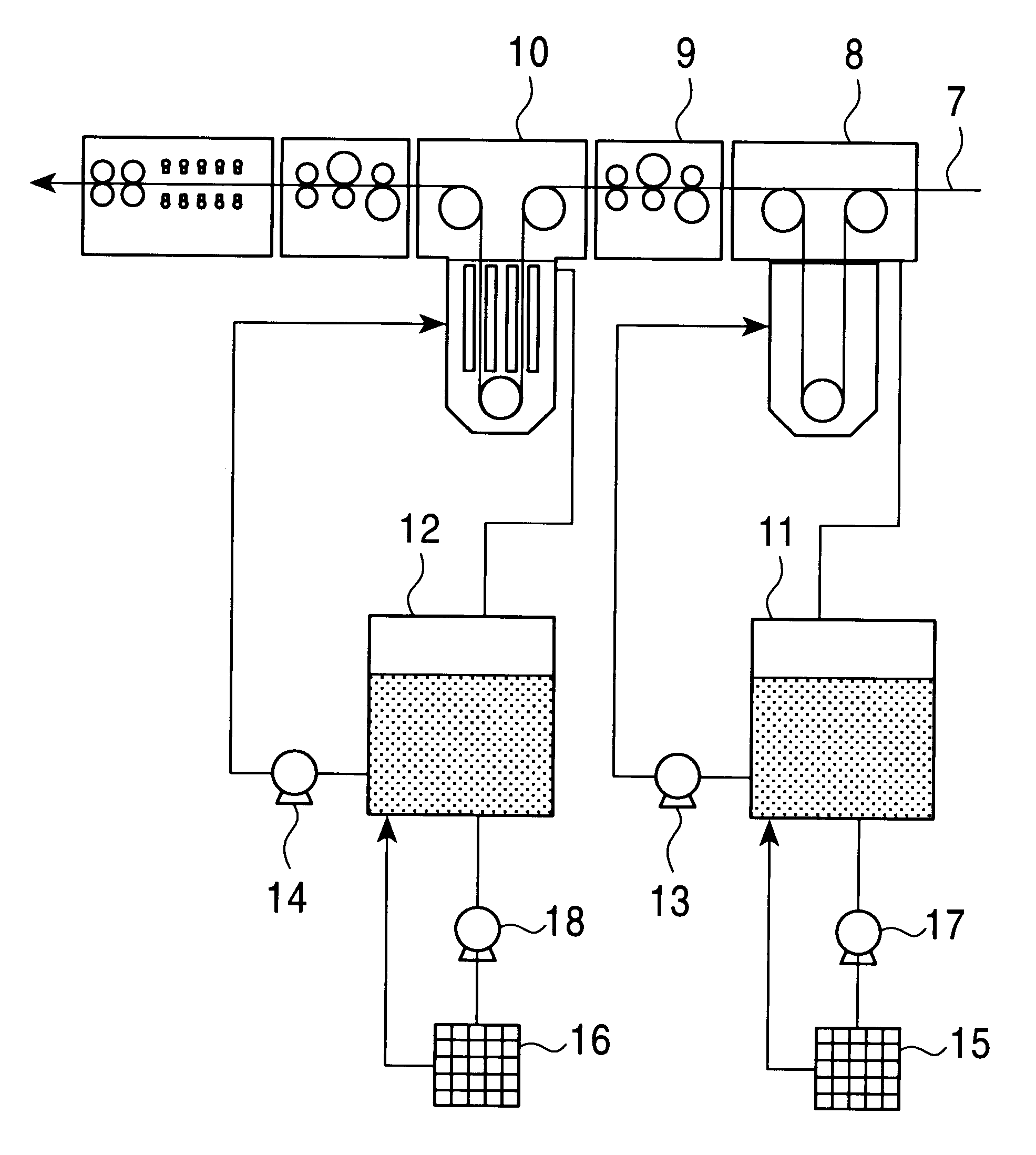
Cleaning treatment of the washing liquid was performed using magnetic filter apparatuses of the present invention in actual cleaning equipment shown in FIG. 9.

As shown in the drawing, a steel sheet 7 after rolling was passed through a rough washing tank 8, usually called a dunk-tank, brushed by a first brush scrubber 9, and subjected to main washing in a cleaning tank 10.

The dunk tank 8 and the cleaning tank 10 were provided with circulating tanks 11 and 12, respectively, and a washing liquid mainly constituting an alkaline washing liquid was circulated using pumps 13 and 14.

The washing liquid in the circulating tanks 11 and 12 was fed to magnetic filter apparatuses 15 and 16 using pumps 17 and 18, respectively, to attract and separate the iron particles removed from the steel sheets during cleaning.

The specifications of the magnetic filter apparatus 16 for the circulating tank of the cleaning tank, the filter passage time of the washing liquid, and the iron particle concentration a...


PUM

PropertyMeasurementUnit
ferromagneticaaaaaaaaaa
residual magnetic flux density Baaaaaaaaaa
residual magnetic flux densityaaaaaaaaaa

Abstract

In a magnetic filter apparatus in which permanent magnets are arranged to oppose each other with a container therebetween so as to generate a magnetic line of force in a direction substantially orthogonal to the moving direction of the fluid in the interior of the container, while regulating a filter passage time of the fluid in the range of 0.5 to 1.5 seconds, the permanent magnets are arranged so that the distance L (mm) between the permanent magnets in relation to the residual magnetic flux density B (T) of the permanent magnets satisfies the relationship:In this manner, the highest possible performance can be obtained from the filter using general-purpose permanent magnets such as ferrite or neodymium magnets, thereby achieving size reduction of the apparatus at low equipment cost.

Description

The present invention relates to a magnetic filter apparatus for continuously separating magnetic particles contained in fluids, which is used in cleaning treatment of various types of fluid such as rolling oil for cold-rolling steel sheets and washing liquids for removing the rolling oil after the cold rolling.In cleaning rolling oil for cold-rolling of steel sheets and washing liquids for removing the rolling oil remaining on the surface of the cold-rolled steel sheets, a magnetic filter apparatus is used to remove magnetic particles contained in the fluids.A typical example of a conventional magnetic filter apparatus is now explained with reference to a cross-sectional view in FIG. 1(a) and a side view in FIG. 1(b). In the drawings, reference numeral 1 denotes a container, 2 denotes a permanent magnet, 3 denotes a filter element, 4 denotes a back plate, 5 denotes a fluid inlet, and 6 denotes a fluid outlet.A ferromagnetic component comprising a metal grid composed of iron or ferr...

Claims


Application Information

Patent Timeline
Patent Type & Authority Patents(United States)
IPC IPC(8): B03C1/033B03C1/02B03C1/28B01D35/06B03C1/00B03C1/14B21B45/02
CPCB03C1/288B03C1/0332
Inventor IIDA, SACHIHIRONAKAGAWA, KENJIUENO, NAOTOKATO, KATSUHIKO
Owner JFEENG CORP
Why Eureka
Try Eureka