Bi-directional short pulse ring laser

a laser and short pulse technology, applied in the direction of laser details, optical resonator shape and construction, electrical equipment, etc., can solve the problems of linearity, gyro becomes more cumbersome, and linear response is still not guaranteed

Inactive Publication Date: 2003-11-18
STC UNM
View PDF97 Cites 28 Cited by
  • Summary
  • Abstract
  • Description
  • Claims
  • Application Information

AI Technical Summary

Benefits of technology

Reducing dead band can comprise predetermining and controlling the time at which the bi-directional pulses are launched so that they do not cross at any component within the laser cavity that could cause scattering of the light. Controlling the pulse crossing point can comprise control via traveling wave gate or traveling wave gain. Controlling the launch time can comprise controlling with unidirectional amplification such as with an optical parametric oscillator or with doped gain fibers pumped by a short pulse. Controlling the launch time can alternatively comprise controlling the timing in either direction by a directional optical gate. Controlling with a directional optical gate can comprise controlling a modulator within a fiber laser by providing a first electrical pulse to switch on the modulator and allowing light to pass through the gate in one direction, and then providing a second electrical pulse to switch the modulator, thereby allowing light to then pass in the opposite direction to the first. Alternatively, controlling by unidirectional amplification can comprise the steps of providing a ring laser with bi-directional synchronous pumping and controlling the pulse crossing point with optical delay lines. The ring laser can comprise an optical parametric oscillator that is pumped in two directions by a pulsed laser and preferably the optical parametric oscillator is periodically poled. The method further comprises the steps of using the optical parametric oscillator near degeneracy and reducing the fundamental noise limit by using the idler output instead of the signal through output mirrors.
FIG. 8 shows a simple laser cavity wherein the nonlinear element is located 1 / 4 cavity length away from the gain medium;
FIG. 16 shows an arrangement to measure the relative phase of a pulse with respect to its envelope in accordance with the present invention; the optional four prism arrangement is to minimize the duration and eventual phase modulation of the pulse probing the nonlinear medium;

Problems solved by technology

The first problem is that of linearity.
Of course, one consequence is that the gyro becomes more cumbersome due to the mechanical dithering devices.
In addition, the gyro response near the dithering frequency does not reflect the "actual" rotation rate .OMEGA.. Hence, the linear response is still not assured.
These gyros are plagued by a dead band, even using very expensive optics that have much less scattering than normal mirrors.
It defeats the purpose of making a laser gyro, if moving parts are to be used.
Further, vacuum tubes such as He--Ne lasers are an obsolete technology.
The electrodes have a short lifetime and the laser itself has very low efficiency.

Method used


Image

  • Bi-directional short pulse ring laser
  • Bi-directional short pulse ring laser
  • Bi-directional short pulse ring laser

Examples


Embodiment Construction

)

1. Solid State Laser Gyro with Nonlinear Crystal

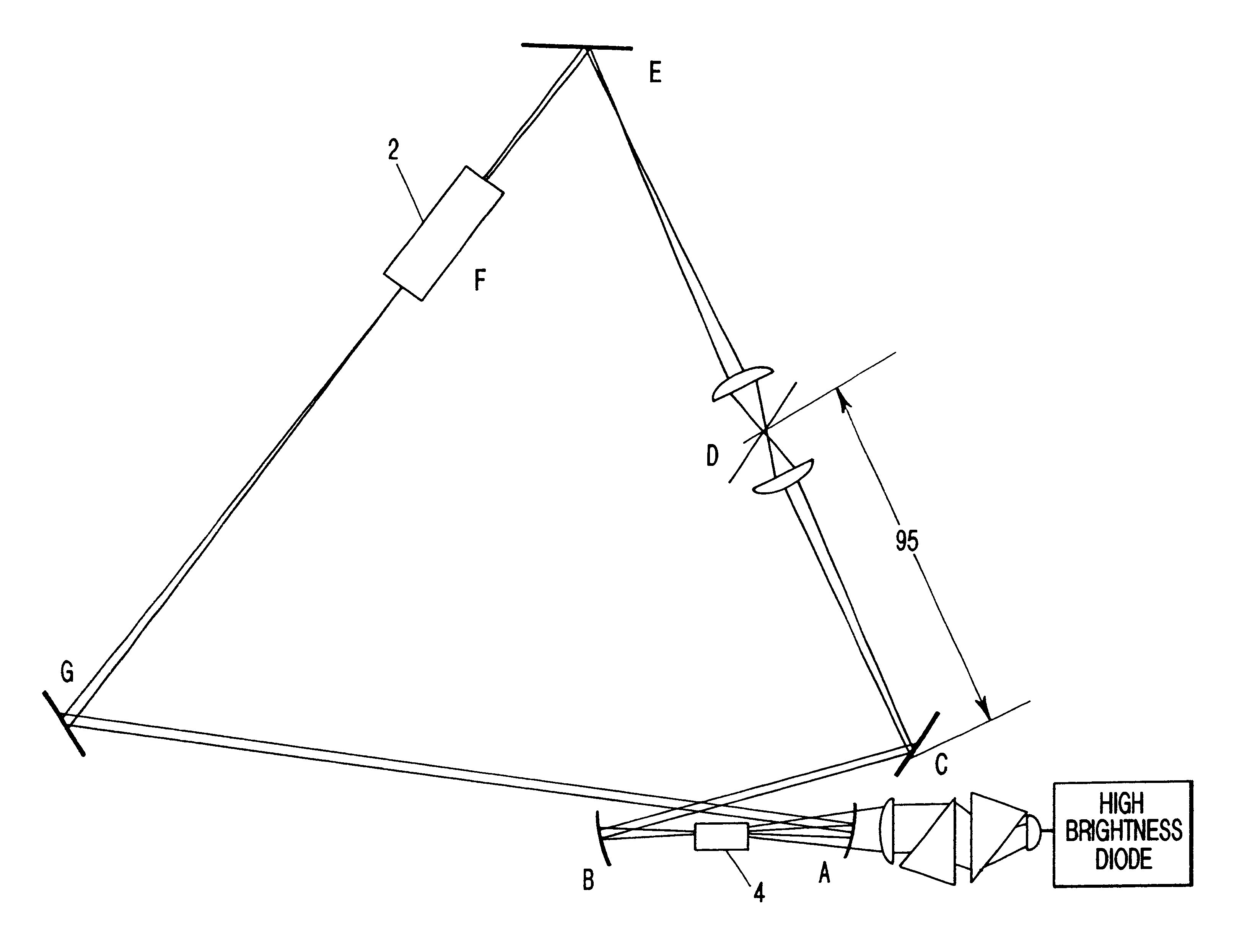
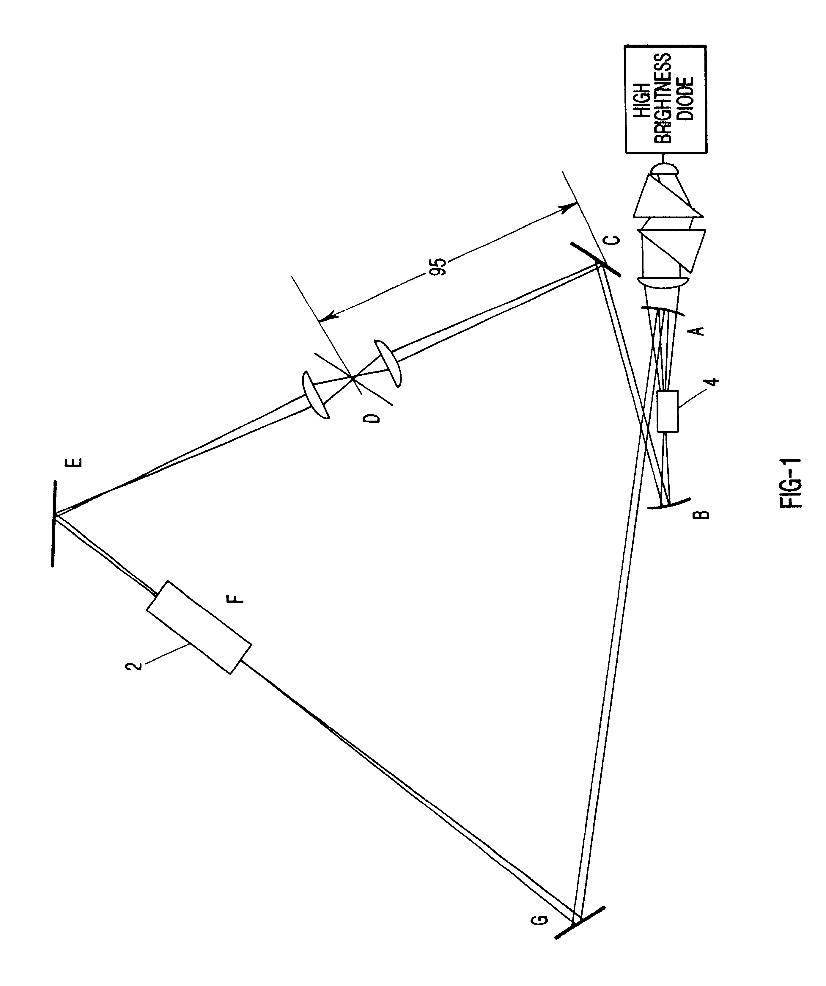
In the first embodiment of the present invention, a short pulse ring laser gyro is implemented, in which the mechanism for making short pulses is nonlinear-interaction of the counter-propagating beams in a nonlinear crystal. The nonlinear crystal is located in a beam waist of the cavity, or in the proximity of a beam waist. The short pulses are generated through a self-lensing effect in the nonlinear crystal. Because of the intensity dependence of the index of refraction in these crystals, a Gaussian shaped beam profile induces a lens in the nonlinear medium. The effect of this lens is to increase or decrease the beam diameter at some other part of the cavity. By inserting an aperture at some location of the cavity where the beam diameter decreases with intensity, short pulse operation is favored, since the losses decrease with intensity. This effect is enhanced if two pulses cross in the crystal. Therefore, the crystal becomes the me...


PUM


Abstract

A bi-directional pulsed ring laser that produces bi-directional light pulses that interact in such a way that they are phase conjugated. A nonlinear substance, such as a nonlinear crystal or fluid, that has an index of refraction that is dependent upon light intensity is located near a beam waist of the laser cavity to provide a self-lensing effect. Methods for reducing dead band beyond observable limits are also provided. The increased sensitivity of the bi-directional pulsed ring laser provides application in detecting magnetic susceptibility by detecting the change in phase between the arrival times of the bi-directional pulses at a modulator and the electrical signal of the modulator to determine the change in frequency of a coil that has magnetic susceptibility.

Description

1. Field of the Invention (Technical Field)The present invention relates to the field of short pulse ring lasers and applications therefor.2. Background ArtNote that the following discussion refers to a number of publications by author(s) and year of publication, and that due to recent publication dates certain publications are not to be considered as prior art vis-a-vis the present invention. Discussion of such publications herein is given for more complete background and is not to be construed as an admission that such publications are prior art for patentability determination purposes.The gyroscope (gyro) has been in use for navigational purposes since the 1920's, its accuracy improving as technology advanced. Today's state-of-the-art gyroscopes use two counter-propagating beams of continuous wave (CW) light in a ring configuration and take the beat frequency .DELTA..upsilon. between the two beams to be a measure of the rotation rate .OMEGA..The principle behind the laser gyro is...

Claims


Application Information

Patent Timeline
Patent Type & Authority Patents(United States)
IPC IPC(8): G01C19/64G01C19/66H01S3/081H01S3/083H01S3/108H01S3/098
CPCG01C19/66H01S3/1112H01S3/108H01S3/083
Inventor DIELS, JEAN-CLAUDE M.DANG, THIEN TRANGJONES, R. JASONBOHN, MATTHEW J.
Owner STC UNM
Why Eureka
Try Eureka